

Introduction: IOS-Controlled Arduino Waveform Generator


This waveform generator is based on the work by Amanda Ghassaei. Waveform generators (or function generators) are used for testing and debugging circuits. e.g. frequency response of op amp or sensors. This waveform generator is powered by Arduino with Annikken Andee shield - a device that lets users create iOS/Android interfaces without iOS or Android programming at all. It outputs sine, triangle, saw and square waves. Frequency is controlled by means of a slider (on iOS/Android device) and wave type is selected using on screen iOS/Android button. With a iOS/Android interface, you can add certain features not possible with hardware buttons. E.g. displaying different ranges of frequencies for each wave type, displaying meaningful controls for certain wave types. For example, the pulse width modulation slider is only visible for square wave types, its not visible for sine, triangle or saw wave forms.
Parts List:
(1x) Arduino Uno or compatible board element14 #2075382
(1x) Annikken Andee for iOS or Android www.annikken.com
(1x) Prototyping Perfboad element14 #1536938
(25x) 10Kohm resistors element14 #9339060
(1x) 10-way female connector element14 #1815119
Wire/breadboard jumper wires. Soldering equipment.
Attachments

Step 1: Build a Simple R2R DAC


Build a R2R DAC using the schematic provided. Note that all the resistors used are 10Kohm.
Step 2: Solder 10-way Connector

Solder on a 10-way connector for jumper wires to attached to the R2R ladder. Make the correct connections from 10-way connector to the corresponding resistors. Leave pin 10 of the connector unconnected. Solder wires for OUTPUT and GND to make connections to an oscilloscope for viewing.
My setup here does not include the following:
- Low-pass RC filter.
- Voltage follower to buffer the output, you have to add this before using the output on any of your testing circuit.
- Gain control using LM386 - to adjust the peak-to-peak amplitude of the output waveform.OUTPUT and GND to make connections to an oscilloscope for viewing.
However, its enough to show a waveform on the oscilloscope.
Step 3: Connect Annikken Andee and Arduino

Connect Annikken Andee to Arduino by simply plugging it on top as a shield.
Step 4: Connect Arduino and R2R Ladder
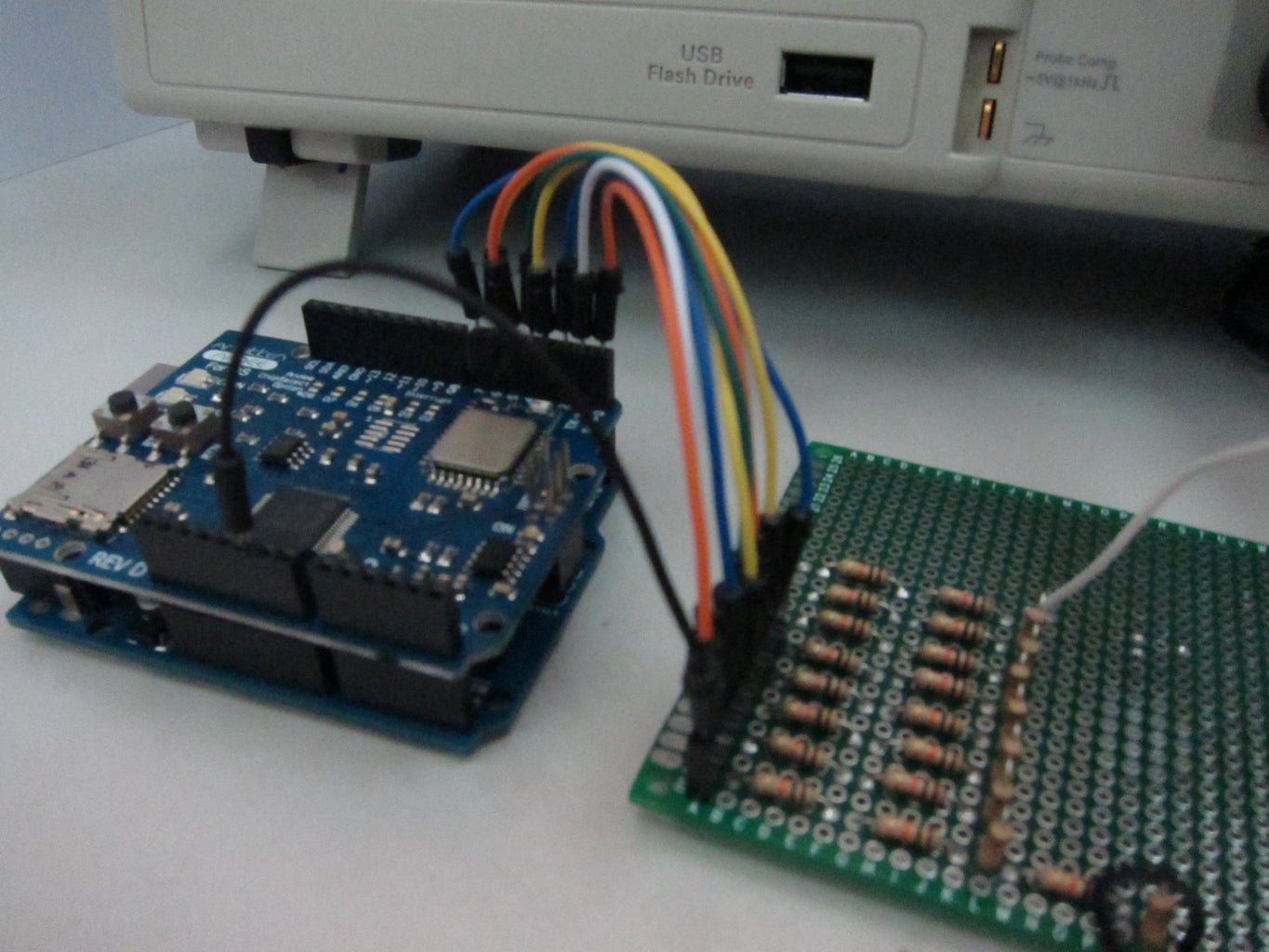
Connect pins 0 to 7 of Arduino to pins 0 to 7 of the R2R ladder we soldered earlier. Connect Arduino GND to R2R's GND.
Step 5: Arduino IDE Setup - Part 1

- Download and install Arduino IDE (if you have not)
- To use Annikken Andee, you need to install a library containing helpful functions for you to draw interfaces on iOS/Android. Get it from www.annikken.com
- Click on the link "Click here to download zip file". The library is in the form of a zip file. E.g. Build_18.zip.
Step 6: Arduino IDE Setup - Part 2
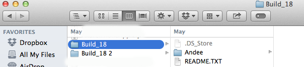
- Unzip and copy the folder named "Andee" found inside the unzipped folder.
- Paste it inside the Documents->Arduino->libraries folder.
Step 7: Step 4: Arduino IDE Setup - Part 3

Start or restart Arduino IDE and you should see Andee examples installed.
Step 8: Download Arduino Code
Download the Arduino code "function_generator2.ino".
You need to create a folder named "function_generator2" inside your Arduino sketchbook folder. The location is usually found at Documents/Arduino.
Paste the "function_generator2.ino" inside "function_generator2" folder.
Start or restart the Arduino IDE.
You should be able to open the code from File->Sketchbook->function_generator2.
Connect USB to your Arduino, compile and upload the code.
Attachments

Step 9: Annikken Andee App


Download the free Annikken Andee app from either the Apple App Store or Google Play Store.
I will be showing the iOS example in this instructable.
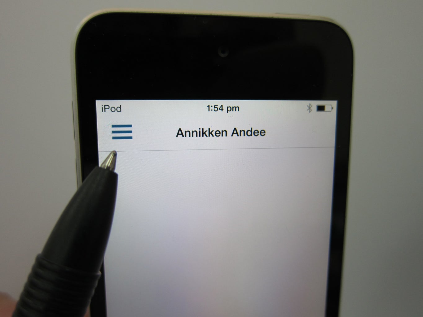
- Install and launch the app.
- Press the MENU button (3 horizontal lines) .
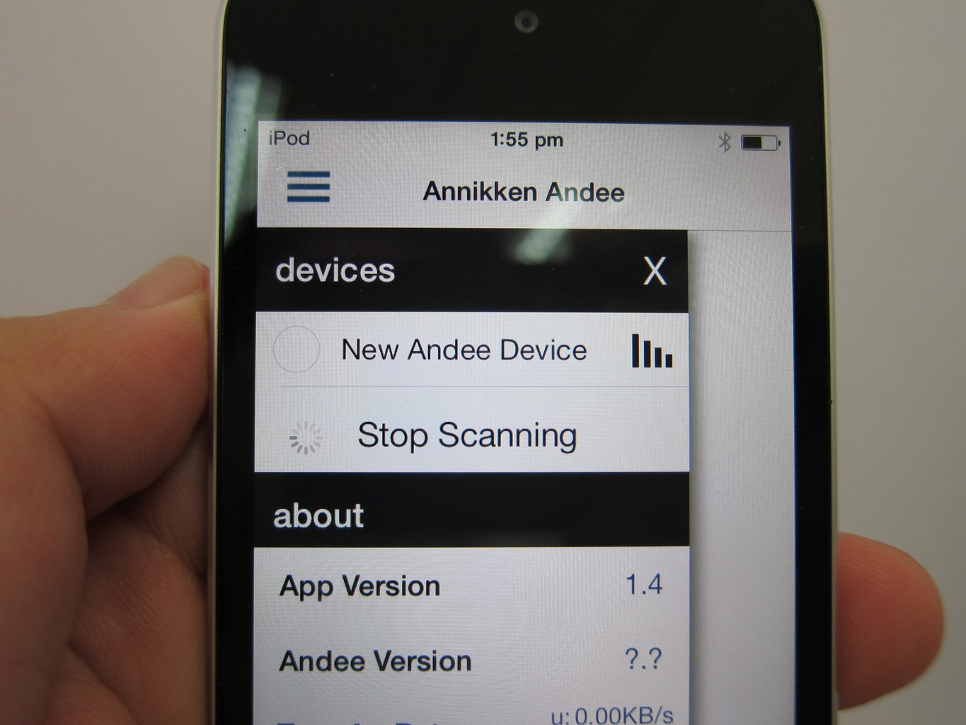
- Press "Scan new devices"
- You should see your Annikken Andee after some time. In this case, it has the name "New Andee Device"
- Press on the "New Andee Device" and you will be prompted with a connection dialog.
- Press "Connect". Some time later your screen (as defined in your arduino code) will appear.
Step 10: Connect Output to Oscilloscope and Have FUN!
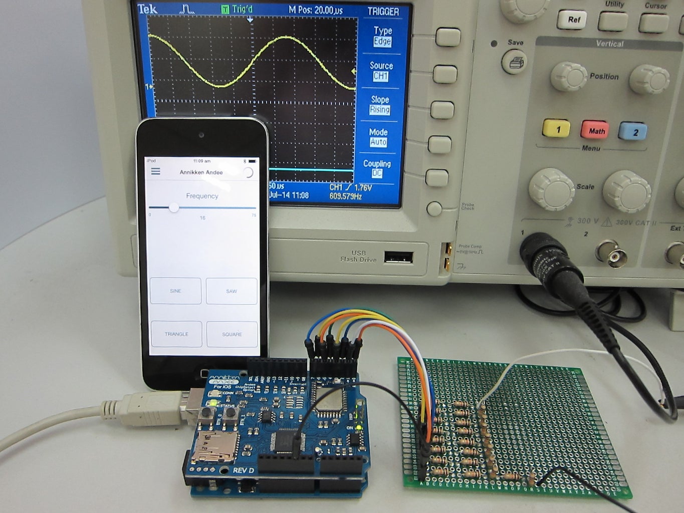
Connect output of your R2R ladder to an oscilloscope. On your iOS screen, select "SINE" and shift frequency to about 20, and see the waveform appear on your oscilloscope.
On iOS, choose waveform by pressing on the buttons, and also adjust frequency using the sliders!
HAVE FUN!


