

Introduction: Augment Your Reality With the ITorch Raspberry Pi Flashlight Projector


UPDATE: May 3rd - Playing Minecraft on the newer iTorch :)
UPDATE: NEW iTorch 3D printed version! && Finally uploaded some videos, hope you like them. :)
Post by ITorch Media Sharing.
https://www.facebook.com/photo.php?v=292394047593097
iTorch
Media Sharing
Created By: Travis Higgins
This Instructable is for a prototype homemade projector that can be illuminated by any decent LED flashlight/floodlight.
This is my first published instructable so please leave comments and/or suggestions! Any feedback is very welcome and I will try to respond to everyone as soon as I see it!
At this stage the iTorch is a kit that I hope to be able to make available if I were to somehow get my hands on my own laser cutter. I have been spending a good amount of money using school equipment to laser cut this project, and got a quote to use the 3d printer and the price was astronomical. So needless to say a laser cutter and 3d printer would go to good use and be greatly appreciated.
Though you could probably reverse engineer one of your own. ;)
I designed the iTorch to be a portable and wireless projection system that would allow a user to freely project their media wherever they choose. I am currently working on integrating the iTorch into a gaming platform where the iTorch is both the viewing device (tv) as well as the controller!
The concept for the iTorch came from trying to find a financial solution for another larger scale project I had been working on. A interactive and holographic environment that would have required the use of several costly projection systems.
However financing the project has been an issue. So I tried to redesign the installation on a smaller scale. Though a small scale solution may have conveyed the idea, it would not have allowed anyone to have the full experience.
I needed projectors, and they aren't cheap, so I thought I would build my own.
In creating these projectors I came up with the idea for a portable battery powered projector that was illuminated by the power of a flashlight.
From personal experience with projection, and researching the purchase of several projector units I found that the main issue for projector longevity were their bulbs. The light bulb in a projector seems to be the most common part to break or burn out in the life of a projector, but with the iTorch - if you have another flashlight you are good to go!
The iTorch design was created and built by Travis Higgins for a capstone project in New Media at the University of Maine. In development of virtual reality shared experiences (shared augmented reality). The iTorch was designed to be a portable and wireless projection system that would allow a user to freely project their media ( or augmented data) wherever they choose.
Links:
https://www.facebook.com/ITorch
http://www.higginscapstone2014.blogspot.com
Email:
mrtravishiggins@gmail.com

Step 1: Parts!


https://www.facebook.com/photo.php?v=292315317600970
This Instructable does require a little bit of technical skill (disassembling LED screen) and if you are trying to build it from scratch it will take a little bit of math and access to a fabrication lab.
It takes an hour to cut the wood into a kit in the laser cutter. I use a 4' x 2' piece of Birch that I cut down to 24" x 18" to fit the laser bed. It's $10 a sheet at Home Depot, and costs $10/hr to use the laser cutter.
I've been using aluminum foil from my kitchen for the reflective siding in the light box. So I don't count that.
The Flashlight cost around 50$ + $40 for the batteries and charger I believe. Those can vary.
The 12V fans I get at RadioShack for $16 today, I think they were on sale the first time I went. You can get the male to male couplers there too for about $6-7. I also get the 5V USB rechargeable power bricks there too insanely cheap, usually on sale, today I got one for 4$.
The LCD panel is a 2.0'' TFT from Adafruit at a hefty 45$.
Raspberry Pi at a lovely $35.
SD card 10-20$
So here are the parts you will need to build your own iTorch!
(1)- iTorch assembly kit - (coming soon!)
- Main Body Assembly (body,lcdholder, lens holder)
- Flashlight Holder Assembly (varies depending on flashlight type, for this 'able I'm using the 'SuperBright')
- Raspberry Pi Assembly
(1) Flashlight - For this instructable we are using the SuperBright LED flashlight. - $45-50 + batteries
(1)- Raspberry Pi model B - http://www.element14.com/community/community/raspb... $35
(1) - USB bluetooth & wifi combo - $20ish
(1) - USB storage flashdrive - $10-20
*(1) - SD card for RPi OS or multiple RPi OS's - $10 - 20
(1)- 2.0" NTSC/PAL (Television) TFT Display - 2.0" Diagonal http://www.adafruit.com/products/911#tutorials - $45
(1)- 9v battery
(1)- 12v 8-AA battery holder & 8AA batteries - $4 for the holder
(atleast 1) - camera lens - I used a Canon macro C lens and another Canon lens, the lens cap i used works for both.
(1) rear lens cap for the camera lens you are going to use. I got mine from GoodWill for like 10$, was a Canon SLR.
(1)- 5v Enercell 5v 800mah PowerBank http://www.radioshack.com/product/index.jsp?produc... $5-15 usually on sale
Tape - painters or electrical.
(1) 12VDC microfan http://www.radioshack.com/product/index.jsp?produc...
** velcro!
Tools:
Laser cutter
Tape
Dremel
Step 2: Main Body Assembly


In your iTorch Kit you will have a 'Main Body Assembly'.
Included in the MBA will be:
- four side panels (top, bottom, fan, other)
- (4) fillets for the flashlight holder
-(1) stopper/fillet for the flashlight holder
- (1) LCD frame
- (1) Lens Mount / Raspberry Pi mount
First you will want to line up the four 'Side Panels' like in the photos. They will interlock.
Make sure that the small fillet holes on either end match up!
Step 3: Inserting LCD


1) Locate the LCD frame holder.
2) You will notice the front of the LCD frame holder has been etched out to hold the LCD panel as well as accommodate for the controller board wiring. ( When you get to inserting the LCD panel be very careful it is very fragile!)
3) Place the LCD holder into the 'Top Panel' center fillets as shown in the photo's. The FRONT of the LCD holder should be facing the closest edge. (as pictured) This edge is where the Camera Lens will be.
4) Place side panels into interlocking positions as shown.
Taping can be useful, but the body should snap together quite nicely and hold.
Step 4: Main Body Sides


This step is easy.
As long as you have the side panels linked as shown in the previous step, you should be able to simply fold them up and snap them right into place.
Use tape if necessary to hold in place for the time being.
*** It's at this point where you would want to line the Light Box portion of the Main Body with tin foil, and also insert the MicroFan into the Fan Side Panel. However, I don't yet have photos of this. Though it is fairly common sense, and it is not a difficult process, I would like to have photos to show you how. And I will shortly :) ***
*** Test fan before installing to make sure the air is blowing OUT not back in! ***
Step 5: Lens Mount / Pi Holder


Last step for the Main Body is to attach the Lens Mount / Pi Holder
Make sure that the Fan Side Panel is on one of the sides, doesn't matter left/right, and that the Top Panel slit is up.
Tape to secure.
Step 6: Flashlight Mount


Here we will place the fillets that hold in the Flashlight Mounts, the holes for the fillets are located at the rear of the iTorch just behind the fan.
Depending on what type of flashlight you have you may have a different size/shape fillet assembly, as the iTorch can have flashlight mounts for many types of flashlights.
Parts: From Main Body Assembly
(4) Flashlight Mount fillets
(1) Flashlight Stopper/fillet
1 - The 4 fillets fit snuggly into the inner fillet holes of the 4 Side Panels. In the picture above I show the easiest way to get all 4 in at the same time.
2 - Slightly loosen side panels at the rear of the iTorch body assembly (opposite of lens holder).
3 - Insert all 4 fillet inserts into the inner fillet holes as shown in photos.
4 - close main body assembly, might have to wiggle fillets a bit to get them to slide in.
5 - place the Flashlight Stopper/Fillet into the notches remaining in the rear.
Step 7: Main Body Complete

Your Main Body Assembly should now look like this!
Step 8: Flashlight Holder Assembly


Now that you've completed the Main Body Assembly we are going to put together the Flashlight Mount for your flashlight.
For this instructable we will be using the Mount for the SuperBright LED flashlight.
In the Flashlight Holder Assembly you will find:
(2) Flashlight Holders
(4) Flashlight Holder Panels
This step doesn't need a lot of explaining. The Mount, like most of the iTorch can only be assembled one way, and fits together nice and snug.
1 - Fit one of the Flashlight Mount Panels to the fillets located at the rear of the Main Body Assembly. On the bottom works best (shown in photos).
2 - Insert a Flashlight Holder into the inner set of holes of the Flashlight Mount Panel you attached.
3 - attach the remaining 3 Flashlight Mount Panels as shown. Simply line up the holes, the panels will only fit on one way.
4 - insert the remaining Flashlight Holder to the remaining holes/slots of the Flashlight Mount Assembly as shown.
You can secure with tape or glue if you plan to use only one type of flashlight.
Step 9: Raspberry Pi Assembly


For the Raspberry Pi Assembly, I simply modified a file from thingiverse to fit to my iTorch body assembly. Link coming when I find it again. I also had to modify it to the type of wood I use because of the thickness I had to modify nearly the entire case in order to get the pi to fit.
The Raspberry Pi assembly has:
1 - Top & 1 - Bottom
2 - sides (component side & hdmi )
1 - back panel (usb / ethernet)
the front is part of the LENS holder, so don't worry about that ;)
Step 1 - You're going to want to start with the back panel (usb/ethernet) its the tightest fit.
2 - Wiggle back panel onto your Raspberry Pi.
3 - Now attach the HDMI panel, you may want to tape it.
4 - Insert the bottom panel into the corresponding holes on the HDMI panel.
5 - You can now put on the Composite and Audio Panel. You may want to tape this also.
6 - Finally, add the top panel.
You should now have a Raspberry Pi case with 3 sides, a top and bottom and NO front.
Step 2 - Set to the side for now.
Step 10: Inserting LCD Panel


This part can be a little tricky, and where technical know how comes into play.
1 - The LCD panel needs to be disassembled. (photos coming soon, couldn't do this one handed)
First you should remove the LCD from the controller board. (detach the thin sheetlike wire)
The tricky part is removing the LCD digitizer from its aluminum/plastic casing.
If you got the 2.0" TFT LCD from my link, it should be fairly easy. Simply loosen the tabs holding the LCD to the aluminum casing and gently pry the LCD forward. There might be glue holding it in in some cases, in which case you should use a sharp edge or credit card to separate the glue from the LCD.
Be careful removing the Fresnel and Diffusers from the LCD, depending on your flashlight you may want to use these later on.
( If you're not familiar with Camera Obscura it may be confusing why we need to do all this. With projection, the Image is flipped and reversed, so we need to do the same to the LCD to give us a normal image.)
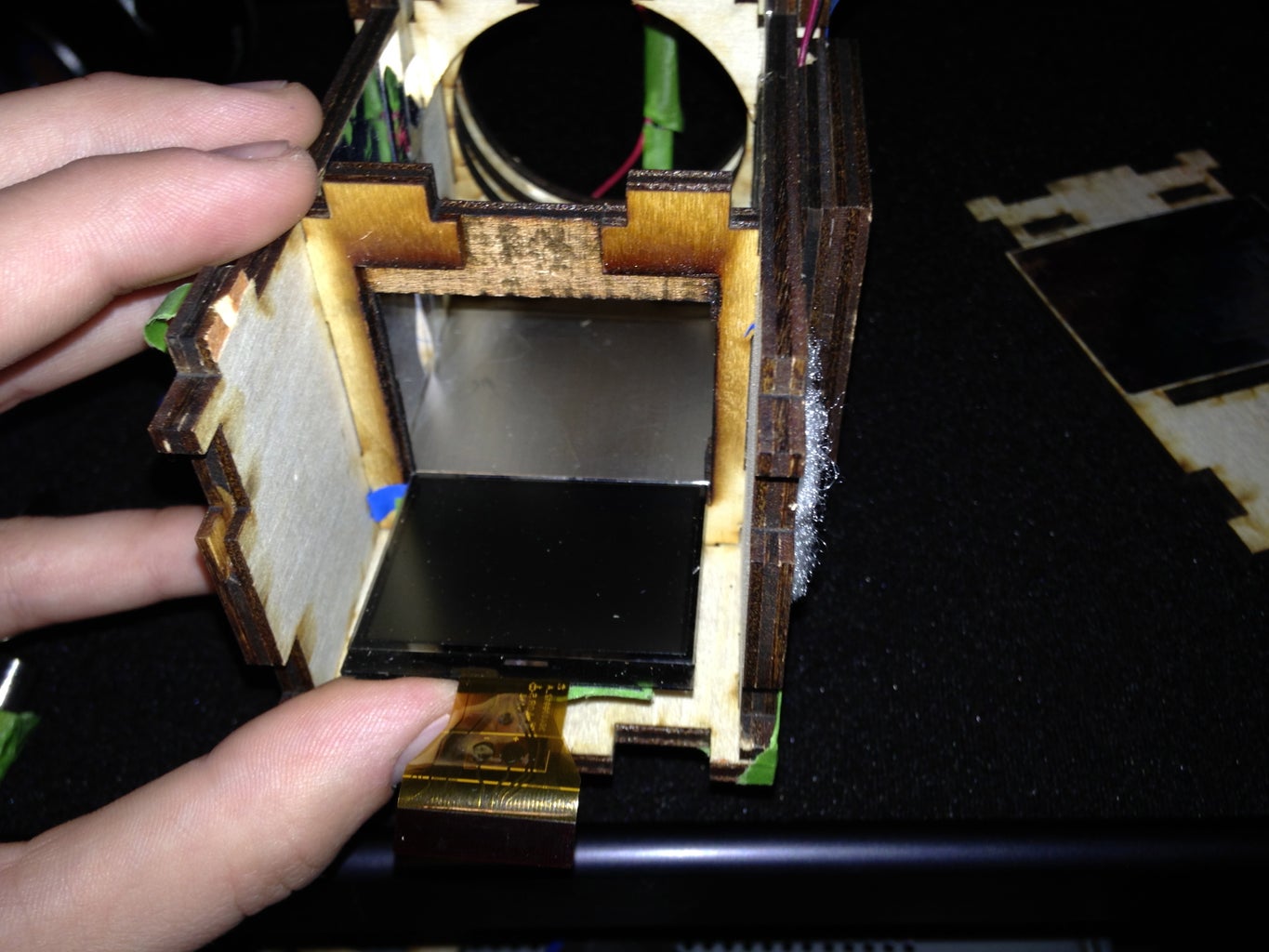
2 - Once the LCD and ribbon are free from the casing you can insert the LCD as shown into the LCD Frame Holder of the Main Body Assembly.
Make sure to place exactly as shown in the photo!
The back of the LCD is now the front, as well the bottom is now the top.
3 - Secure lightly around the edges with tape.
4 - Now slide the ribbon through its hole in the Top Panel of the Main Body.
5 - If you had to loosen the sides to get your fingers in there that's ok, just tighten it back up and move on to step 6.
6 - Using double sided tape you can attach the LCD controller board to the Top Panel in its etched-out position.
7 - Connect the LCD ribbon to the controller board.
8 - Now you can re-attach the Lens Holder mount.
Almost Done!Step 11: Pi 2 ITorch


Remember that Raspberry Pi Assembly, well it just slides right into the Lens Holder.
You can take the lens holder off to attach the Raspberry Pi case or leave it on, its not hard either way.
You may want to tape, its not as tight as the rest of the build.
Step 12: Lens Mount


https://www.facebook.com/photo.php?v=292392617593240
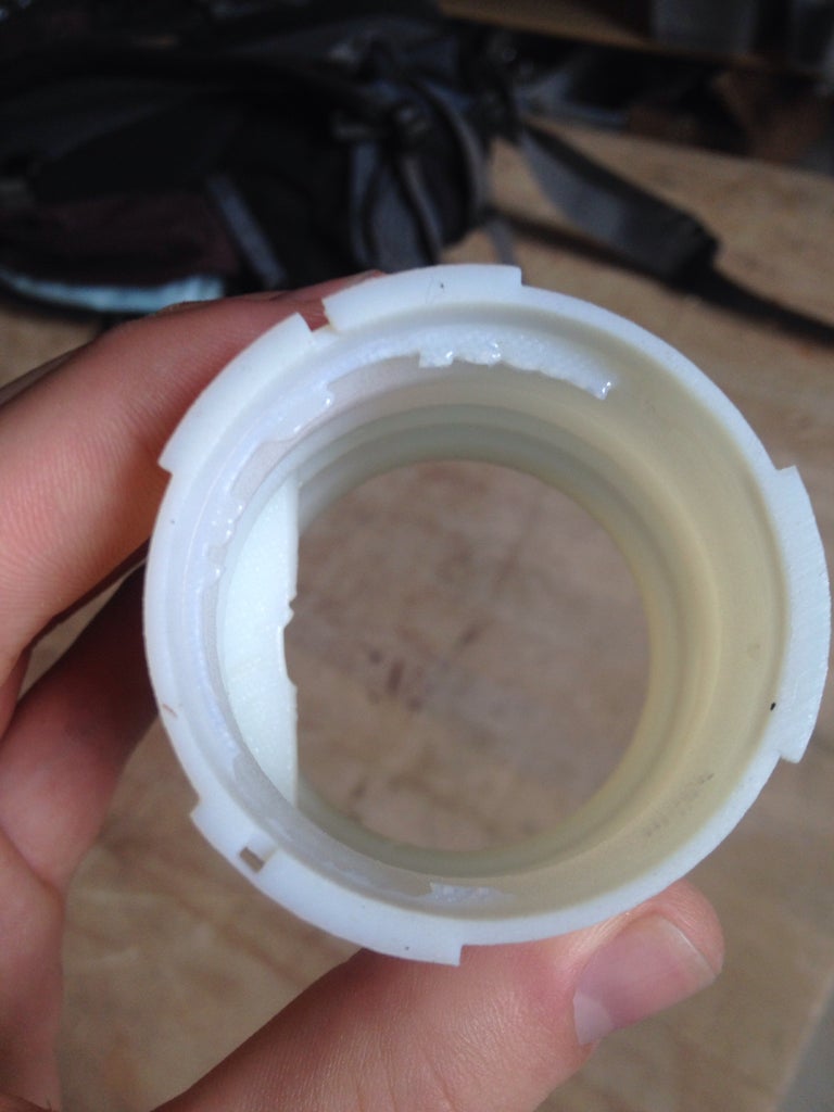
This is the only thing you will need to fabricate on your own with this kit.
For this step all you need to do is remove all but the walls of the rear lens cap.
What should remain of the lens cap is a ring and the locking mechanism. (photo)
Then simply slide it into the hole of the Lens Mount Panel.
You can now attach and interchange lens' that fit that style/brand lens.
Step 13: VELCRO
No photos really.
I used velcro to attach all of my batteries and battery packs.
5V rachargeable - on top of RPI case
9V LCD PWR - on Side Panel
12V fan batteries - on Bottom Panel
Step 14: Attach Lens

Your lens should twist right in like it would if you were attaching it to a camera and detach the same as well.
Step 15: Raspberry Pi Setup


Now if you didn't buy a Pi with a SD card already formatted for you, you're going to have to do that to get the pi working.
I would suggest running NOOBS for first time users, and XMBC or Raspbian for an OS.
http://www.raspberrypi.org/introducing-the-new-out...
You will need SDFormatter to format your SD card. All the instructions can be found through raspberry pi user community forums.
XMBC will allow you to quickly get in to playing movies or slideshows instantly on your iTorch.
* You have two USB ports available with the Raspberry Pi
I used one of these slots for a Wifi/Bluetooth USB module so I could control the iTorch with a mini keyboard mouse.
This is an iTorch instructable not a Raspberry Pi instructable, however if you have any questions feel free to ask. ;)
Step 16: Get It All Connected and Powered Up!
1st - Plug in the 9V power source to your LCD power. ( Power on ).
2nd - Insert SuperBright LED flashlight into flashlight mount.
3rd - Power up the Raspberry Pi with the 5V 850mah rechargeable PowerBank from radioshack. (powerOn RPI).
4th - Plug in/power on Fan for cooling.
5th - Turn on SuperBright flashlight and have fun! :)

Third Prize in the
Full Spectrum Laser Contest

Participated in the
Gadget Hacking and Accessories Contest


