

Introduction: Open-source CNC Project


![Fun & easy sailboat [Protei 009.1]](https://content.instructables.com/F3E/MYWG/GYKQ5G8K/F3EMYWGGYKQ5G8K.jpg?auto=webp&crop=1%3A1&frame=1&width=130)
C i C is a low cost, easy to assemble and an open-source CNC platform.
What is the purpose of C i C?
The intention of the C i C is to provide students (of the department of Industrial Design) with an accessible platform from which they can explore different manufacturing opportunities and learn about electronics, mechanics and software.
How is the C i C an open-source platform?
The entire frame of the C i C is made by laser cutting 6mm MDF, which makes it easy to replace bits and modify them using any CAD program. When I finished the entire assembly I will upload it here so anyone can download the plans.
What are the capabilities of the C i C?
That is a very short answer; I don’t know! Experimenting with the machine will give some answers. The goal is to be able to do isolation engraving for PCB’s and foam cutting but it might be used for 3D printing and 3D carve shaping.
I divided this instructable in three main parts, the first is the mechanical part of the cnc machine, the second part is the electronics used to drive the cnc stepper motors and such, the third part is where I explain all the software bits.
Step 1: The Mechanics


First image is the assembly view of the C i C in Solidworks (z-axis and train are yet to be modeled!)
Next picture: close up of the frame; using widely available (skateboard) bearings (blue) and aluminium corner profiles (red). This rail system ensures smooth movement of the trains and no movements in other directions other then the rail.
Last picture shows M8 thread with a skateboard bearing which happens to fit nicely! (Both are cheap and compatible!)
UPDATE (see picture)
Since the laser cutter that would cut out the parts for my cnc machine broke down for a couple of week I had the opportunity to reflect on the original design and make some changes:
Go from a M8 lead screw to M5 to overcome difficulties coupling the lead screw to the stepper motors. (shaft of the stepper motor is 5mm)
Redesigned the x-axis, originally dust and material could get stuck in the rail or in the leadscrew, the new design prevents this by having side slots from which it is harder for dust and material to get in. (it also increases the workable area)
Generalized the lengths of all the bolts, just two major sizes: 16 and 25 mm.
Some other small improvements!
UPDATE II
Finnaly received the laser cut MDF parts today! yeay! Started assembling the parts, i'm going to cut rails and lead screw to length very soon. Hope to receive the bearing in the mail sometime this week so hopefully I will have a moving x-axis this weekend!
After assembling the x-train/y-frame I discovered some movement in the parts, if this is unsolved it would resolve in a major accuracy problem in the y-axis. I already know how to fix the problem though, I will laser out some more parts to stiffen the two colloms of the y-frame.
I made some pictures of the progress so check those out!
If you happen to have power supply for free laying around in the house, please donate it to me ;)
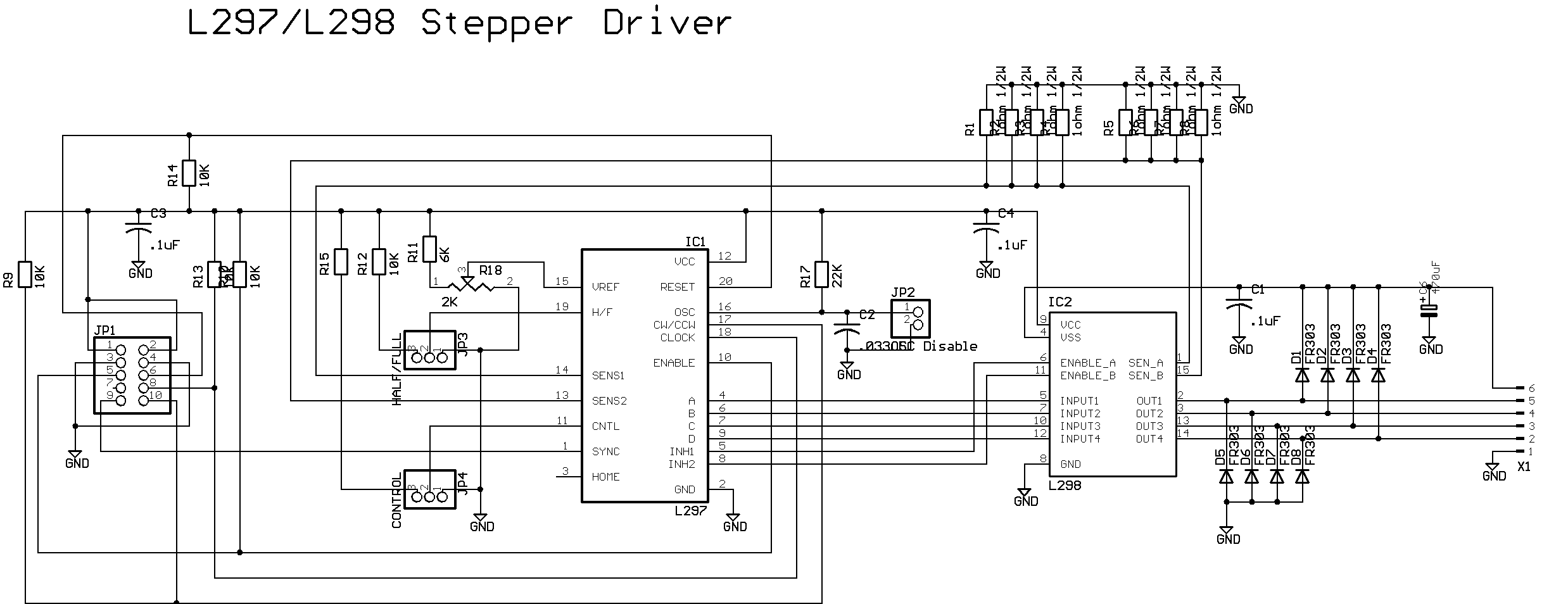
Step 2: The Electronics


Received the stepper motors today and the parts for the drivers, all on one day! It took me about 5 hours (excluding mapping the components and figuring out where all the wires should go) to solder the driver. I based my circuit on this diagram, however I made some changes, when I have some time to make my own in Eagle I will upload them! During the first test, the power indicating led didn’t work, oops, wrong polarity! After that I hook up an Arduino to it and a power supply for the motors, written a quick program and eureka! It works like a charm! For this small test I used 0.5 A per winding (which is 25% of the power I am planning to use, more power is more torque) and 5 volt (which is 20% of voltage I am planning to use, more volt = more speed). The speed and torque of the motor in this test was already impressive, can’t wait to see it in ‘full’ mode.
Here are some pictures of the test:
Step 3: The Software
I downloaded the G code interpreter for Arduino and ran a test with it, result: works perfectly! What I will probably do is hack into the code and get rid of the stuff I will not use. You can find the G code interpreter here.


