

Introduction: RSkin - Open Source Robot Skin


While this Instructable documents the process of building a fully functioning 28 x 28 pressure sensitive matrix, there is much room for improvement, and so in each step we discuss issues with the current solution and also include suggests for improvements. At this stage in the project we are really looking fwd to receiving your feedback and suggestions! Ian is also looking to hire individuals interested in (re-)building the skin based on this Instructable (changes, alterations, improvements encouraged!), so if you are interested in taking on this challenge, please contact us through Instructables. Please note that the skills required to replicate the current version of rSkin include: hand and machine sewing, soldering and a basic understanding of the electrical properties of materials.
The next step this Instructable explains in more detail the basic principal of how rSkin works without going into the full amount of detail required to build it yourself. Before attempting to remake this Instructable, i would recommend reading through all the steps to get a good impression of how it all comes together. Building rSkin is not necessarily a linear process where everything needs to happen in a particular order, though in this Instructable i make an attempt at doing just that.
rSkin project progress blog >> http://www.plusea.at/?page_id=2259
Here are some videos of the results of the current version of rSkin:
Ellipse Visualization
Heat-Map Visualization
Gray-Scale Visualization
rSkin Links:
Project Page
Progress Blog
Flickr Photo Set
GitHub Code Repository
YouTube Playlist
Step 1: Pressure Sensor Matrix (an Overview)


rSkin is a pressure sensitive grid made of conductive, non-conductive and piezoresistive fabrics. While the grid described in this Instructable is 28 rows x 28 columns large, ideally it can be scaled up to cover much larger areas.
rSkin is made of stretchy materials so that it can fit tightly over the robot arm. The conductive rows and columns are sewn using a conductive thread to adjacent pieces of non-conductive stretch materials (base substrates). Stretchy piezoresistive fabric is sandwiched between the conductive rows and columns, and acts as a pressure sensitive layer. Piezoresistive materials have the property that their electrical resistance decreases under under mechanical stress, such as pressure.
The photo included in this step shows the conductive rows and columns made from strips of conductive fabric sewn to their base substrates with a regular (non-conductive) thread. This photo was taken during the prototyping stage and while it nicely shows the layering of the skin (the white layer is flipped to face the pink layer), in the final version we sewed the conductive rows and columns using conductive thread, rather than using strips of conductive fabric. Our choice to use the thread instead of the fabric, came because by minimizing the conductive surface (a strand of thread is thinner than a strip of fabric), we increased the range of pressure sensitivity through the piezoresistive fabric.
Once the fabric part of the matrix is constructed, the rows and columns are individually connected to in/outputs of a microcontroller that acts as an analog to digital converter. Because there are more rows and columns than most microcontrollers have pins for, we use multiplexers to increase the number of in/out connections. But essentially what we we are doing is powering the rows one by one, while reading analog values (pressure information) from the columns one by one. Because we know which row is powered and which column we are reading from, we know where (location information) the incoming analog value is located. This all happens really fast, so that we can parse through the whole grid in multiple times in less than one second - giving us the impression that it is all happening instantaneously.
The mircrocontroller (in our case a Teensy) is programmed to parse the rows and columns and collect the pressure and position data, sending it over the USB connection to the computer where another application (written in Processing), reads the string of data and translates it into a visualization by mapping the incoming values to their corresponding position on the robot skin, and shading, colouring or drawing shapes according to the pressure information.
The row and column solution is not the only possibility we explored when approaching this project. The Piezoresistive Touchpad was among our first trials, but it does not support multi-touch.
Terminology (for clarity):
* Base substrates: non conductive materials.
* Flesh: lower base substrate made of neoprene with conductive columns machine sewn with conductive thread.
* Skin: upper level base substrate made of durable double knit stretch fabric with conductive rows machine sewn with conductive thread.
* Base: end of robot arm opposite the hand. This is where all the row and column connections terminate/accumulate and make the connection to their hard circuitry.
* Far end: opposite base end of robot arm. This is where the robot hand is with its two fingers.
* Hand: robot hand that has two fingers.
* Fingers: individual parts of the robot hand.
* Traces: i refer to the rows and columns as traces, they are conductors analogous to wires.
Step 2: Materials and Tools

The following Sparkfun wishlist contains the items relevant to building rSkin that Sparkfun sells (They don’t sell nearly everything!!!), but some of them you will get cheaper and better elsewhere. See bellow for details.
Sparkfun rSkin wishlist >> http://www.sparkfun.com/wish_lists/30564
Materials for Skin
* Neoprene
we used: Neoprene, 0.5mm thick with stretch fabric fused to only one side
taken from a neoprene vest top:
>> http://www.wetsuitoutlet.co.uk/billabong-girls-equator-neoprene-vest-05mm-blackpink-r4eq07-p-3111.html
roughly $30 + 5$ shipping
The advantages of neoprene are that it has great recovery after stretch (it does not stretch out easily) and it has enough thickness and isolating properties so that sewing connections on one side, and overlapping ones on the other does not result in unwanted interconnections between sides. What is nice about this particular neoprene is thin and rubbery on one side. Which means that is bunches minimally at the joint when bent, and clings nicely to the robot arm, keeping it from sliding around.
You could also use:
A thicker neoprene (1mm, 1.5mm or even 5mm), and it could also have fabric on both sides. If it moves around too much you could add some latex or rubbery glue to it, to give it some grip. Though beware not all sewing machines like thicker neoprenes! You could also use other materials. My main reason for choosing neoprene was because it allowed me to sew sensor column connections on one side and overlapping connections from each column back to one end on the other side without electrically touching. Also, because it has a stability to it that helps "fill" some of the gaps in the robotic arm, that would otherwise have no counter-pressure.
* Double Knit Fabric (roughly $10/yd)
From a good local fabrics store. You can also use other stretch fabrics in place of this. You want something that will keep its shape and can hold a zigzag stitch.
Hancock Fabrics >> http://www.hancockfabrics.com/
* Piezoresistive fabric (EeonTex LG7436 SL-PA-10E5 Batch:RP-4-64-2B)
free sample from Eeonyx.
* Thin conductive thread (roughly $30)
Conductive thread 117/17 2ply manufactured by Shieldex, sold by Sparkfun and Silverell.
>> http://www.sparkfun.com/products/8544
>> http://www.fine-silver-productsnet.com/22coagya.html
Dowload datasheet from Shieldex >> http://www.shieldextrading.net/pdfs/11717x2.pdf
While this thread is nice and thin, it also breaks and frays easily. It oculd be nice to replace it with a stronger thin thread. Finding an alternative thread that is solderable, would also offer some more possibilities for connecting it to the hard circuitry.
* Regular sewing thread (roughly $2 - $5)
Local fabric or craft store or online.
>> http://www.hancockfabrics.com/Sew-All-Thread-273-Yards---Nu-White-Gutermann_stcVVproductId47568117VVcatId539563VVviewprod.htm
* Flat Ribbon Cable (roughly $1 - $27)
Local electronics store or online.
sparkfun (rainbow, regular) >> http://www.sparkfun.com/products/10649
digikey (through-hole spacing!) >> http://search.digikey.com/us/en/products/8125%2F10%20100/ML10G-10-ND/2658738
* Breakaway Male Headers (roughly $3)
Local electronics store or online. Used to connect from the ribbon cables to the breadboard. These become obsolete if all circuitry is permanently wired.
Sparkfun (male) >> http://www.sparkfun.com/products/116
Sparkfun (female) >> http://www.sparkfun.com/products/115
* Perforated Circuit Board with line pattern (roughly $4 - upwards)
Also called “Perfboard” or “Solderable Breadboard”. Radioshack sells these.
Maplin >> http://www.maplin.co.uk/matrix-boards-47480?ordercode=N95CF
Amazon >> http://www.amazon.com/s/ref=nb_sb_noss?url=search-alias%3Delectronics&field-keywords=perfboard&x=0&y=0
All Electronics >> http://www.allelectronics.com/make-a-store/category/455/Perf-Boards/1.html
Radioshack >> http://www.radioshack.com/product/index.jsp?productId=2102843#
* Aleene’s stretchy fabric glue (roughly $4)
For isolating conductive thread, sealing knots and stopping fraying. Sold in local fabric or craft stores as well as online.
Hancock Fabrics >> http://www.hancockfabrics.com/Aleene-s-Flexible-Stretchable-Fabric-Glue---2-Ounces-Liquid-Adhesives_stcVVproductId47609184VVcatId540047VVviewprod.htm
* Solder (roughly $7)
Local electronics store, Radioshack or online.
>> http://www.radioshack.com/product/index.jsp?productId=2062717
Materials for Multiplexer Circuit
* Teensy, a/d converter, programmable microcontroller (roughly $16 - 20)
Adafruit >> https://www.adafruit.com/products/199
pjrc >> http://www.pjrc.com/store/teensy.html
* Mini USB cable (roughly $4)
Local store or online. Check, maybe you already have one!
>> http://www.sparkfun.com/products/598
* Four 16 Channel Multiplexers, part number: CD4067BE (roughly $1 - $3 each)
Also called Mux, Demux. From local electronics store or online.
ACK supply >> http://www.acksupply.com/
Digikey >> http://search.digikey.com/scripts/DkSearch/dksus.dll?Detail&itemSeq=106014348&uq=634545300981007248
Sparkfun (surface mount!) >> http://www.sparkfun.com/products/299
* Two 10K potentiometers (roughly $1 - $3 each)
These can be replaced by fixed resistors once you know the best value. Local electronics store or online.
>> http://www.sparkfun.com/products/9288
* Breadboard (roughly $12)
Local electronics or online.
Sparkfun >> http://www.sparkfun.com/products/112
* Jumper wire (roughly $3)
Local electronics or online.
Sparkfun (jumper wire kit) >> http://www.sparkfun.com/products/124
Sparkfun (hook-up wire) >> http://www.sparkfun.com/products/8024
Tools
* Sewing Machine (roughly $120)
You want a sewing machine that can handle heavier fabrics (neoprene) and do a zigzag stitch.
SINGER 4411 Heavy Duty Model Sewing Machine
>> http://www.amazon.com/SINGER-4411-Heavy-Sewing-Machine/dp/B003VWXZKG/ref=sr_1_2?ie=UTF8&qid=1322065538&sr=8-2
* Good fabric scissors (roughly $10)
Local fabric or craft store or online.
Amazon >> http://www.amazon.com/Fiskars-8-Inch-Multi-Purpose-Scissors/dp/B000OMWGNS/ref=sr_1_3?s=arts-crafts&ie=UTF8&qid=1323195535&sr=1-3
* Sewing needles (roughly $2)
Local fabric store or online.
* Soldering Iron (roughly $30)
I use a Weller WLC100 40-Watt Soldering Station
Amazon >> http://www.amazon.com/Weller-WLC100-40-Watt-Soldering-Station/dp/B000AS28UC/ref=sr_1_cc_2?s=arts-crafts&ie=UTF8&qid=1322065637&sr=1-2-catcorr
* Needle Nose Soldering Tip (roughly $5)
Weller Tip, Soldering, Conical For WP Series Irons, 1/32" >> Amazon >> http://www.amazon.com/Weller-Tip-Soldering-Conical-Irons/dp/B0007IS2J6/ref=pd_sim_ac_6
* Seam ripper (roughly $2)
Local fabric store or oline.
* Paper, pens
* Cutter knife
* Glue gun and hot glue sticks
* Pliers
* Printer
* Computer
* Arduino software
* Processing software
Step 3: Making Stencils and Preparing Materials


The first step in the process, after picking your materials, placing orders and finally receiving everything, is to prepare stencils for the three layers of fabric that make up the rSkin.
The following A3 size PDF contains stencils for the flesh, skin and piezoresistive layers. These stencils can be printed out 1:1 and transferred directly to the materials. They indicate row/column spacing and counts, as well as how the rows and columns connect electrically to the rest of the circuitry.
Because rSkin is handmade, it is highly customizable and you may want to make changes to the stencils provided in order to incorporate customizations, improvements or adjustments.
Download A3 stencil (PDF) >> https://github.com/iandanforth/rSkin/blob/master/pdf/rSkinA3.pdf
The measurements in the PDF stencil indicate distances to seams in cm. You will want to add a seam allowance to this, depending on how much your comfortable sewing with. I normally add roughly 5mm, which is indicated in the stencil as an additional outline. After cutting out the shapes of the materials, also trace your rows and columns, as well as their connections to the perforated circuit board (perfboard). To make makings on the materials either use a soft pencil or purchase fabric chalk or markers.
Reasons to alter the stencils:
* Fit
The stencils included here are tailored to the elasticity (stretchiness) of the specific materials i used (see Step 2). If you are using different materials, then you want to make sure the width and length of these stencils will work for you. If your robot arm is smaller or larger than the arm we used (described here: http://makeprojects.com/Project/Build-an-Arm-for-Your-TurtleBot/1323/1) then you will need to adjust the stencils. You want the skin to fit well, but also "relaxed". You don't want the initial pressure of the skin being stretched over the skin to max-out your range of pressure sensitivity.
* Number of rows and columns (surface area covered, resolution)
If you have to sew the skin tighter or less tight, to make your particular fabric fit your robot arm then you will need to scale or reduce the number of rows accordingly. But you might also want to increase or decrease the number of rows or columns to adjust the resolution to fit the needs of your particular application. When scaling down to smaller intervals, you want to make sure you can maintain a safe electrical distance between traces - which basically means no touching, or finding a way to isolate them.
* Spacing between rows, columns (resolution)
Whether or not you need to adjust the circumference of the skin to fit the arm, you can choose to increase or decrease the spacing of the rows (and columns) to match your desirable resolution. Part of the reason the version of rSkin documented through this Instructable is a 28x28 grid, was to save on production time. Ideally i think a 0.3 or 0.5 mm spacing would be ideal for “pretty-high resolution”. Although, ideal spacing depends greatly on the types of objects you're interested in detecting. If you want to detect the pressure of fingertips touching the skin, then it does not make sense to go bellow a certain resolution because the tip of any finger is already a certain size. The spacing of your rows and columns also depends on the base substrates and possibly other pressure distributing materials used to make the skin. Thin materials contain the pressure to defined areas, squishy materials distribute the pressure to surrounding rows and columns.
* Widths of rows, columns (sensitivity, resolution)
Another thing to consider are the actual widths of your rows and columns. In the version described here the rows and columns are sewn with conductive thread with a roughly 4mm wide zigzag stitch. The zigzag stitch makes the traces stretchy, which is essential since the base materials themselves are stretchy and so the traces need to stretch with them. The zigzag pattern also acts a bit as a space filling curve, that minimizes conductivity, but somewhat evenly covers a specific area (width of trace). While i chose to sew a zigzag stitch to cover at least some width, i am sure there are other ways of creating these stretchy conductive traces that are more robust.
Side-note: The current design is 28 rows in circumference, where each row is spaced 5mm apart (total circumference = 14cm), while the columns are spaced 1cm apart, covering a length of 28cm. The reason for spacing the columns further apart had two reasons. The first was because each column needs to electrically connect back to a central point (one end of the skin), and in this design these connections were sewn on the back of the fabric, which was coincidentally half as wide (rows) as it was wide (columns), so that these connecting rows that lead to each of the columns were spaced 0.5cm apart which was deemed a safe spacing distance to the risk of avoid unwanted interconnections. The second reason was simply to minimize the number of connections that needed to be sewn to save on time in production.
Step 4: Machine-sewing Flesh Columns (and Connector-rows)


Set your sewing machine to sew a zigzag stitch that is roughly 4mm wide and 4mm lenght. Sew the columns on the fabric side of the neoprene first, and then sewing the column-connecting-rows on the rubber side of the neoprene. See stencils for details.
When sewing the columns start at one end of the fabric and sew to the other. You can immediately cut the thread short and you don't need to double back on yourself to keep it from undoing, as i would recommend using some glue on all terminations to keep the thread from fraying.
Once all the columns are sewn, go back and sew the rows that connect from each column to the base end of the sleeve. Start sewing at the column end of the trace and sew a zigzag stitch (this one can be narrower, so long as it stretches nicely with the neoprene) all the way to 1 cm past the first column, then (without removing the fabric from underneath the sewing needle!!!) switch your sewing machine setting to a straight stitch and continue to sew to the connection on the perforated circuit board. See the following video for details.
Because you will be attaching both ends of these rows make sure to keep both of them long (at least 10cm!). And keep them out of the way when sewing preceding rows so as not to trap loose conductive thread ends under the stitch, as this can separate it and in the worst case means you need to cut that thread short and re-connect to it with a knot or multiple stitches (which is annoying).
Video
TEST!
After sewing all your traces, take out a multimeter and set it to measure continuity. Measure for unwanted connections between all columns, all connector-rows and then between columns and connector rows. If you find a bad connection, you want to find exactly where it is and fix it right away before continuing to the next step. This might involve undoing the column or connector-row and re-sewing it.
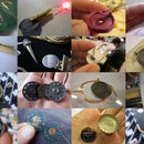
Step 5: Hand-stitching Column Connections
Once you have machine sewn all columns and connected them to their connection-rows you're now ready to connect the connection-rows to the perforated circuit boards that you can then solder wires to. Hard soft connections (fabric/thread to circuit board/wire) are some of the trickiest steps when working with these materials, and doing them well, can make all the difference in achieving a good, reliable electrical connection.
For each column connector row we have two connections to hand sew. First sew the connections from the connector row to the column, these are stitched through the fabric and with at least 5 very small stitches make a connection between the threads.
After sewing all these connections, use a tiny bit of glue to seal the end of the thread so that it will not come undone or fray.
Step 6: Hard-Soft Connections


Before we can sew the connections from the connector-rows to the perforated circuit boards we need to prepare the circuit boards. To cut the perfboards to size use a cutter knife to score them and then pliers to snap off the scored pieces. Use a file to sand all edges and corners of these perfboard pieces as any sharp edges will tear the thread!
When sewing the connections between the thread and the perfboard, make sure to sew at least 5 times around the circuit board and then instead of tying a knot, sew back into the neoprene along the same stitch (as shown in photo) and then cut the thread close to the fabric.
After sewing all conductive thread ends to the perfboard, either use some regular sewing thread to sew the other sides of these perfboard to the neoprene for extra stability and strain relief, or use hot glue between the perfboard and the neoprene.
Apply the fabric glue thickly to isolate the threads where they are sewn with a straight stitch, as this is not part of the sensitive matrix, and will only cause additional noise between readings. If the fabric glue is not isolating enough, you can add an additional thin layer of non-conductive stretch fabric on top of the glue. You can also try using other castable silicons or rubbers to isolate the threads and act as a strain-relief on the hard-soft connection between thread and perfboard.
Step 7: Sewing Flesh Together


Once all your columns and column-connectors are sewn and connected to each other and to the circuit boards, you are ready to sew the flesh together.
The flesh layer is sewn together into a tube and then the fabric flaps at the far end are folded over and sewn to make pockets for the robot fingers of the hand. First fold the fabric in half (fabric sides facing in, rubber sides facing out) along the symmetry axis (see stencils) and sew the first seam along the length of the arm. Then fold over the finger flaps (see stencil) and sew these together, fabric side facing in, rubber side facing out.
I used a straight stitch to sew the seams and pulled slightly back at the fabric as it was feeding into the sewing machine to insure that the seams would be able to stretch with the fabric after they were sewn.
If you have problems sewing the double layers of neoprene with the sewing machine you can also sew them by hand, and even get rid of the seam allowance as you are able to sew the edges of the neoprene side by side when sewing by hand.
Even though the stencil shows a seam allowance for the arch shaped pieces of fabric that are sewn into the hand, i did not sew these by machine, but instead sewed them by hand.
In the current design, these pieces of fabric are non-sensitive areas and you will use them as base material to sew additional conductive thread connections from one finger to the other. Maybe you already noticed that not all the columns on either finger are connected by connector-rows to the perfboards. These unconnected columns are not part of the sensitive area and in order to make them connected, the current design sees that these be sewn to one another by hand as shown in the photos bellow. But still, some of the columns at the finger-tips have no fabric bridge between fingers to use for this connection, and i still have not decided on a way to best connect them.
Step 8: Sewing Skin Rows and Connections


Now the flesh layer is complete and the next step is to sew the skin layer, which is very similar to the flesh layer except that it has less interconenctions and will be easier.
Start by setting the sewing machine to the same 4x4mm zigzag stitch and sewing the rows, starting at the far end of the arm and approaching the base. Do the same thing as before and switch from zigzag to straight stitch 1cm past the first column. Leave the threads long at the base end so that you can stitch them to the perfboards, but you can cut them short at the far hand end and use glue to keep them from undoing.
TEST!
After sewing all your rows, test them with the multimeter to make sure they are not connected to each other, and if they are then find out where and fix it before proceeding.
Connect the skin rows to the perfboards, the same way that you connected the flesh connector-rows.
Stabilize perfboard with additional stitches or hot-glue and use fabric glue to isolate threads.
Step 9: Sewing Skin and Piezoresistive Layers Together


Again, sew the skin layer together the same way you sewed the flesh layer.
And then sew the piezoresistive layer together.
Step 10: Getting Dressed


Once all your layers are sewn you might want to take out your miltimeter again and test to make sure none of the columns or rows are interconnected in ways they shouldn’t be. If all looks good then carefully put the layers onto the robot arm one by one.
Video
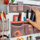
Step 11: Soldering Wires


While you can also do this step before putting the layers of fabric onto the arm, you can just as well do it when they are on, and it somewhat simplifies the “getting dressed” process.
I did not have any double spaced (through-hole pitch, 0.01inch, 2.65mm) ribbon cable, so i used “regular” ribbon cable and skipped every other wire. I separated the ribbon cable into six pieces (4 x 8 conductors, 2 x 12 conductors) that were each 15cm long. You can make these as long as you like, but they should reach comfortably from the base of the skin to your multiplexer circuit.
I stripped either end of each wire and clipped away every other connector, then soldered one end directly to the perfboard next to the conductive fabric stitches (CAREFUL not to touch the thread with the soldering iron as this will burn it away!!!). The other end i soldered to male header pins that can nicely plug into the breadboard.
Step 12: Multiplexer Circuitry


I chose to build my multiplexer circuit on a breadboard, but you can also solder it together on a perfboard, if you like.
All the parts used in the circuit are listed in Step 2) Materials and Tools and bellow you will find images of the schematic and even board layout. From the GitHub repository you can also download the Eagle files.
Eagle Files >> https://github.com/iandanforth/rSkin/tree/master/eagle
Step 13: Programming the Teensy

After building the multiplexer circuit, connect the Teensy to your computer with the mini USB cable. Download and install the following:
Arduino >> http://arduino.cc/en/Main/Software
Teensy Loader >> http://pjrc.com/teensy/loader.html
Teensyduino >> http://pjrc.com/teensy/td_download.html
Download the following Arduino code for Teensy and open it in Arduino.
Arduino code for Teensy >> https://github.com/iandanforth/rSkin/tree/master/teensy/a_rSkin4Multi16
From the Arduino Boards Menu select Teensy 2.0 and compile the Arduino code. Then press the button on the Teensy and the .hex file should upload to the Teensy. For more information see:
Getting started with Teensy Loader >> http://www.pjrc.com/teensy/first_use.html
Open the Arduino serial monitor, and If all went well then you should see a 28*28 grid of numbers printing out into the serial monitor window.
When the skin is not connected to the circuitry these numbers should read 0 (LOW), as we are pulling them to GND with out pull-down resistors.
TEST!
Take a long wire and plug one end to one of the active pins of multiplexer 3 or 4 and the other end to one of the active pins of multiplexer 1 or 2. Look at the numbers printing in the serial monitor and one of these numbers should now be at around 1023 (HIGH).
You can parse through the whole grid like this, to make sure all your connections are reading. The next step will be to connect the skin and see if it works!
Step 14: Plugging Connections

Look at the following pictures to see how the connections go. You want to connect your flesh columns (OUTPUTS) to multiplexers 3 and 4 and your skin rows (ANALOG INPUTS) to multiplexers 1 and 2.
Once you have plugged in all your skin connections the numbers in the serial monitor window will be all over the place, ranging from 0-1023.
If you don’t touch the skin then these numbers should remain relatively stable (the same), and pressuring the glove in different locations should result in a change of numbers, though you probably won’t be able to make sense of them.
In the next step we will visualize these numbers, making it much easier for our eyes to parse.
+ I should also include a diagram here of exactly what row/column goes to what multiplexer pin.
Video
Step 15: Running the Processing Visualization


Then download and open the following code in Processing:
Processing code for Visualization >> https://github.com/iandanforth/rSkin/tree/master/vis/p_robotskin_4multi16channel
Close the Arduino serial monitor window and run the Processing code. A new window should open and it should display a heat-map that looks something like in the photos bellow. Pressuring the skin in different locations should correspond to locations in the visualization.
If everything looks to be working, except that some points on the arm don’t correspond to the location on the visualization then you might need to re-map some of the incoming values to their correct location (See next step).
Goal Positioning
Control
Autonomous Motion
Step 16: Re-Mapping Connections


To do this re-mapping, unplug and take off the skin and piezoresistive layers. With the Processing visualization running, plug a long cable into one of your active row multiplexers (3 or 4) and touch it to the sewn columns on the skin as shown in the video bellow. As soon as one of the physical column connections does not show up in the right place in the virtual representation, go into the processing code and exchange the numbers in the “int[][] fleshRef = {....};” array.
Video
Step 17: Future Versions of RSkin


* Stronger conductive thread that tears and frays less.
* Thicker flesh layer (or additional layer beneath flesh) to buffer angular and hollow discrepancies and create a more uniform underlying surface.
* Tighter spacing of rows and columns.
* Chalieplexing to save on number of connections (grid = n * n-1).
* More efficient way to connect columns back to base of skin (could charlieplexing help here?)
* Hard soft connections
The current version is very reliable, but time intensive and tedious to sew by hand. Making these machine sewable to save on time. Here some ideas >> http://www.kobakant.at/DIY/?p=1272
* Column to row-connector connections
The solution described here is the most elegant and minimal material solution i could come up with, though each connection (from column to column connecting row) has to be hand sewn. If this part of the sewing could be done by machine, possibly using a continuous thread to sew both the column as well as its connector-row, it would make things faster and there would be less opportunity for problems - as each connection is susceptible to issues. One idea i have for an alternate solution is depicted in the picture bellow. Basically the flesh base substrate is double the circumference and each column continues on, takes a right angle bend and connects back along the extra fabric. This doubles the fabric, which is not necessarily a bad thing, as it could anyway be a god idea to have additional buffer material to even-out the bumps and hollows of the arm.
* While zigzag stitch extends column width, it is not very uniform. Shorter zigzag stitches will fill the width of the column more, but also increase the area of conductivity.
Video


