

Introduction: Vintage Style Nixie Wall Clock


After the success of my first nixie clock made out from a rosewood block, I decided to lose no time and to carry on with the next one.
As some of you guys already know, or imagine, lately I'm indeed a little bit addicted to nixie-mania.
I've bought many nixie tubes on eBay, and I experienced in electronics so to build my own high voltage power supply and then the ultimate nixie clock circuit.
Digits for this clock are nice rounded and fully transparent IN-4 tubes, the same I used in the first model, but as I previously announced, I aligned them vertically, so to read from top to bottom hours, minutes, and seconds. Indeed you will see the undeniable influence of Max Pierson's vertical clock.
I guide you now through the full process to make your own unique nixie clock.
WARNING: this circuit raises the voltage to deadly 300V so you must avoid to touch contacts while working, I'm not kidding, please BE CAREFUL!
Step 1: The Case and Start Point


Although I was looking for a nice wood case to use as clock case, when I found this ancient wood handrail piece I suddenly pictured the awesome nixie clock it would become.
I didn't have the camera with me, and I drilled the handrail at once, so I can't show you the intact piece. I used 30mm drill bits as for the previous clock, then I cured the wood with woodworm poison since there were some holes in it.
Step 2: Schematic


Since the first nixie clock was already equipped with a very user-adjustable circuit, with predisposition to add RTC module and other external sensors, I kept that same schematic [UPDATE: I added a switch position to keep the chip powered but the digits off, and there is an additional diode, D5, which is identical to the others 1N4001-4004].
If you want to design your own pcb, you can start from this schematic and develop the circuit in 123D circuits, as I explain in next steps. Notice that the 123D circuits is a bit simplified compared with the original one (I removed the 12-35V PSU part and left 9-12V),
Follow notes on pictures to understand better the way to proceed.
Step 3: Carry on With Pcb Designing


The schematic in 123D Circuits is now ready, and you can extract the b.o.m. to order all the components for your nixie clock.
Step 4: Placement and Routing Process

Depending on your case dimensions, you can arrange components in different ways, just try to keep short traces between high voltage components, and use wider traces for power supply current, you can reduce traces width for signals.
in 123D Circuits you have to route traces manually, but the same you have to do in some automatic software if you want to keep very small distances between components.
Since I lost my 123D project due to connection problems (not the entire project, but half circuit was gone...), and since however I already had a pcb ready to print and etch, I didn't carry on with the routing process, but if you reached this step you are definitely able to complete the pcb and order it, you can probably start from my interrupted schematic.
Step 5: Pcb Ready to Order


Here is the completed circuit boards, the first one is the clock "brain", and the second one only is the tube "shield" which connects the many tubes' pins to the main pcb. This shield has to be personalized with right pads' geometry and resistors values to match the tube type you choose for your clock. You can find more details about these calculations in my other step-to-step guides (hv circuit and nixie clock).
If you want to etch your copper boards at home you can use the toner-transfer method. Attached are both top silk and bottom layer (this last ready to be printed with laser printer and transferred to copper).

Step 6: Solder Components


When your boards are etched and drilled (or arrived from 123D Circuits), you can solder all the components. Then cut all the pins which stick out the bottom side.
If you look at the animated gif you'll see that the voltage is set, turning the potentiometer, so that about 180V comes out of the TEST pin. This voltage is a little bit lower on neondots pins (which have a proper resistor) and is about 1/6 of 180V on the other anodes (which are multiplexed to cover all the six digits).
Step 7: The Software
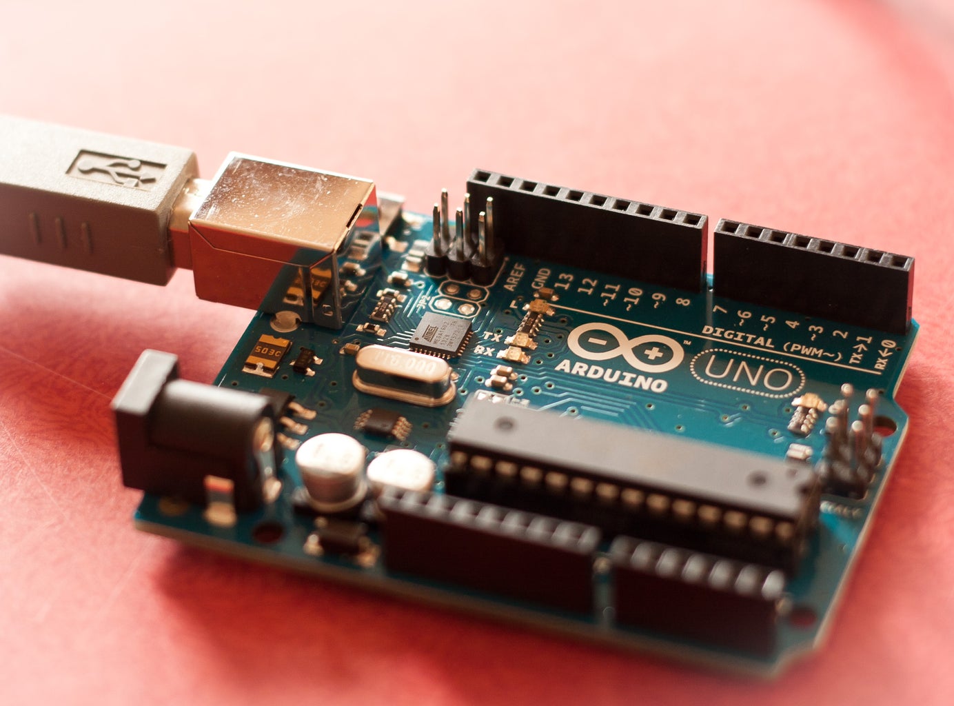
As software I made some modifications to the code used for my first clock (taken from the open source material available on Arduinix website). That code has been modified to use only one nixie driver instead of two, since I don't need to run more than 6 digits, and I prefer to save drivers.. I uploaded the code to the Atmega8 IC using an Arduino board, it's the simpler way in my opinion, but notice that you probably need to burn the bootloader on the new IC to be able to use it in Arduino, I use an USBtinyISP programmer.
NB: I should have implemented the code with RTC feature. Unfortunately some problem have arisen and I'm having some trouble in making it working. One button should increase the hours, and writing new hour in RTC module, other button same thing but for minutes. I hope that some of you more skilled than me (not hard to be) will help me.
// Arduinix 6 Bulb - Also supports Hour and Min. time set.
//
// This code runs a six bulb setup and displays a prototype clock setup.
// NOTE: the delay is setup for IN-17 nixie bulbs.
//
// original code by Jeremy Howa
// www.robotpirate.com
// www.arduinix.com
// 2008 - 2009
// code modified by Andrea Biffi www.andreabiffi.com to work with only one SN74141
//
// Last Edit Nov 2013
//

// SN74141 : True Table
//D C B A #
//L,L,L,L 0
//L,L,L,H 1
//L,L,H,L 2
//L,L,H,H 3
//L,H,L,L 4
//L,H,L,H 5
//L,H,H,L 6
//L,H,H,H 7
//H,L,L,L 8
//H,L,L,H 9

#define DEBUG_ON   false

// SN74141
int ledPin_0_a = 2;
int ledPin_0_b = 3;
int ledPin_0_c = 4;
int ledPin_0_d = 5;

// anod pins
int ledPin_a_1 = 8;
int ledPin_a_2 = 9;
int ledPin_a_3 = 10;
int ledPin_a_4 = 11;
int ledPin_a_5 = 12;
int ledPin_a_6 = 13;

void setup()
{
  pinMode(ledPin_0_a, OUTPUT);
  pinMode(ledPin_0_b, OUTPUT);
  pinMode(ledPin_0_c, OUTPUT);
  pinMode(ledPin_0_d, OUTPUT);

  pinMode(ledPin_a_1, OUTPUT);
  pinMode(ledPin_a_2, OUTPUT);
  pinMode(ledPin_a_3, OUTPUT);
  pinMode(ledPin_a_4, OUTPUT);
  pinMode(ledPin_a_5, OUTPUT);
  pinMode(ledPin_a_6, OUTPUT);

  // NOTE:
  // Grounding on pins analog0 and analog input 1 will set the Hour and Mins.
  pinMode(A0, INPUT ); // set the virtual pin analog0 (pin 0 on the analog inputs )
  digitalWrite(A0, HIGH); // set pin analog input 0 as a pull up resistor.

  pinMode(A1, INPUT ); // set the virtual pin analog input 1 (pin 1 on the analog inputs )
  digitalWrite(A1, HIGH); // set pin analog input 1 as a pull up resistor.

  if( DEBUG_ON )
  {
    Serial.begin(9600);
  }
}

////////////////////////////////////////////////////////////////////////
//
// DisplayNumberSet
// Use: Passing anod number, and number for bulb, this function
//      looks up the truth table and opens the correct outs from the arduino
//      to light the numbers given to this funciton.
//      On a 6 nixie bulb setup.
//
////////////////////////////////////////////////////////////////////////
void DisplayNumberSet( int anod, int num1)
{
  int anodPin;
  int a,b,c,d;

  // set defaults.
  a=0;b=0;c=0;d=0; // will display a zero.
  anodPin =  ledPin_a_1;     // default on first anod.

  // Select what anod to fire.
  switch( anod )
  {
    case 0:    anodPin =  ledPin_a_1;    break;
    case 1:    anodPin =  ledPin_a_2;    break;
    case 2:    anodPin =  ledPin_a_3;    break;
    case 3:    anodPin =  ledPin_a_4;    break;
    case 4:    anodPin =  ledPin_a_5;    break;
    case 5:    anodPin =  ledPin_a_6;    break;
  }

  // Load the a,b,c,d to send to the SN74141 IC (1)
  switch( num1 )
  {
    case 0: a=0;b=0;c=0;d=0;break;
    case 1: a=1;b=0;c=0;d=0;break;
    case 2: a=0;b=1;c=0;d=0;break;
    case 3: a=1;b=1;c=0;d=0;break;
    case 4: a=0;b=0;c=1;d=0;break;
    case 5: a=1;b=0;c=1;d=0;break;
    case 6: a=0;b=1;c=1;d=0;break;
    case 7: a=1;b=1;c=1;d=0;break;
    case 8: a=0;b=0;c=0;d=1;break;
    case 9: a=1;b=0;c=0;d=1;break;
  }

  // Write to output pins.
  digitalWrite(ledPin_0_d, d);
  digitalWrite(ledPin_0_c, c);
  digitalWrite(ledPin_0_b, b);
  digitalWrite(ledPin_0_a, a);

  // Turn on this anod.
  digitalWrite(anodPin, HIGH);

  // Delay
  // NOTE: With the difference in Nixie bulbs you may have to change
  //       this delay to set the update speed of the bulbs. If you
  //       dont wait long enough the bulb will be dim or not light at all
  //       you want to set this delay just right so that you have
  //       nice bright output yet quick enough so that you can multiplex with
  //       more bulbs (2ms is standard).
  delay(2);

  // Shut off this anod.
  digitalWrite(anodPin, LOW);
}

////////////////////////////////////////////////////////////////////////
//
// DisplayNumberString
// Use: passing an array that is 6 elements long will display numbers
//      on a 6 nixie bulb setup.
//
////////////////////////////////////////////////////////////////////////
void DisplayNumberString( int* array )
{
  // bank 1 (bulb 1)
  DisplayNumberSet(0,array[0]);
  // bank 2 (bulb 2)
  DisplayNumberSet(1,array[1]);
  // bank 3 (bulb 3)
  DisplayNumberSet(2,array[2]);
  // bank 4 (bulb 4)
  DisplayNumberSet(3,array[3]);
  // bank 5 (bulb 5)
  DisplayNumberSet(4,array[4]);
  // bank 6 (bulb 6)
  DisplayNumberSet(5,array[5]);
}

// Defines
long MINS = 60;         // 60 Seconds in a Min.
long HOURS = 60 * MINS; // 60 Mins in an hour.
long DAYS = 24 * HOURS; // 24 Hours in a day. > Note: change the 24 to a 12 for non millitary time.

long runTime = 0;       // Time from when we started.

// default time sets. clock will start at 12:59:00
// NOTE: We start seconds at 0 so we dont need a clock set
//       The values you see here would be what you change
//       if you added a set clock inputs to the board.
long clockHourSet = 12;
long clockMinSet  = 59;

int HourButtonPressed = false;
int MinButtonPressed = false;

////////////////////////////////////////////////////////////////////////
//
//
////////////////////////////////////////////////////////////////////////
void loop()
{
  // Get milliseconds.
  runTime = millis();

  // Get time in seconds.
  long time = (runTime) / 1000; ///change this value to speed up or slow down the clock, set to smaller number such as 10, 1, or 100 for debugging

  int hourInput = digitalRead(14);
  int minInput  = digitalRead(15);

  if( DEBUG_ON )
    Serial.println( hourInput );

  if( hourInput == 0 )
    HourButtonPressed = true;
  if( minInput == 0 )
    MinButtonPressed = true;

  if( HourButtonPressed == true && hourInput == 1 )
  {
    clockHourSet++;
    HourButtonPressed = false;
  }

  if( MinButtonPressed == true && minInput == 1 )
  {
    clockMinSet++;
    MinButtonPressed = false;
  }

  // Set time based on offset..
  long hbump = 60*60*clockHourSet;
  long mbump = 60*clockMinSet;
  time += mbump + hbump;

  // Convert time to days,hours,mins,seconds
  long days  = time / DAYS;    time -= days  * DAYS;
  long hours = time / HOURS;   time -= hours * HOURS;
  long minutes  = time / MINS;    time -= minutes  * MINS;
  long seconds  = time;

  // Get the high and low order values for hours,min,seconds.
  int lowerHours = hours % 10;
  int upperHours = hours - lowerHours;
  int lowerMins = minutes % 10;
  int upperMins = minutes - lowerMins;
  int lowerSeconds = seconds % 10;
  int upperSeconds = seconds - lowerSeconds;
  if( upperSeconds >= 10 )   upperSeconds = upperSeconds / 10;
  if( upperMins >= 10 )      upperMins = upperMins / 10;
  if( upperHours >= 10 )     upperHours = upperHours / 10;

  // Fill in the Number array used to display on the tubes.
  int NumberArray[6]={0,0,0,0,0,0};
  NumberArray[0] = upperHours;
  NumberArray[1] = lowerHours;
  NumberArray[2] = upperMins;
  NumberArray[3] = lowerMins;
  NumberArray[4] = upperSeconds;
  NumberArray[5] = lowerSeconds;

  // Display.
  DisplayNumberString( NumberArray );
}
Step 8: RTC Module


Add now the Real Time Clock (RTC) module, soldering four short wires to the corresponding pins on the clock board. Add also some duct tape on the rear of the tubes shield, so to avoid short-circuit between battery and copper traces.
This module will keep (as soon the code will be ready) the exact time when you unplug the wall wart.
Step 9: Pcb Stands

Since I needed a thin frame for the pcb, to let the switch and the buttons sticking out the side of the clock, I decided to use a pair of black plastic bars with L profile. I drilled the holes and finished them off with a small file.
I also had to enlarge the groove on the back of the handrail with an hand milling machine.
Step 10: Glue the Frame


These profiles are glued on the long edges of the main pcb. You also see the power cord extension to transfer the female plug to the bottom of the clock.
Step 11: Obtain the Plates


To cover the top and bottom surfaces of the wood handrail, and to add a touch of style to the clock, I wished to cut a metal plate, but I discovered that a nice black opaque plastic cover is very nice too, and much easier to cut and smooth by hand.
Step 12: Darken the Wood

Where the wood has been cut and smoothed it miss the wax, and is too light, so we have to darken it with brown oil or wax. I also closed the bigger woodworm holes with a proper product.
Step 13: Glue the Plates


After drilling the power jack socket (5.5mm/2.1mm) hole in the bottom plate, and when the oil is absorbed, you can glue the plates on the flat surfaces of the handrail (the "clock" by now).
Step 14: Back Cover


To cover the back side of the clock, and avoid to shock themselves touching the high voltage circuit, we have to make a plastic plate. Four screws will keep the circuit firm in place.
From the junk I keep in my drawers I took out some plastic pieces with handy dimension for this project. Then I cut and shaped them to cover the entire back side of the clock. The long plate is a bit transparent, so to see the handmade pcb.
Step 15: Screws Holes


I drilled four holes for the screws and I made grooves to accept the screws' heads.
Step 16: Gluing


The cover is glued to the back of the pbc, together with the two "L section" plastic profiles and the two drilled little plates. It's better to drill another hole with the typical shape to hang up the clock to the wall.
Step 17: Screwing


After making holes in the wood in the exact positions of the screws you can screw the cover
Step 18: Work Completed


The clock is fully built, you only have to admire it, find a proper wall wart and a place where to hang it up.
Step 19: Connect to Wall Wart


As wall wart you can use any DC power supply from 9 to 12 V (with internal switch setted on 9V) or from 12 to 35V (with internal switch setted on 12-35V). If you decided to go for the simplest schematic you skipped the 12-35V circuit section, so any 9-12V DC PSU is good, with a current flow of 500 mA or more.
[UPDATE: actually leaving the switch to 12-35V position also 9V power works, so if you wish you can add a jumper instead of the switch and power the clock with any voltage from 9V to 35V]
Step 20: Hang It and Turn It On


Hammer a nail in the wall so that the clock will stay in front of the observer, since this type of tubes has a narrow field of vision, especially if the tubes are inserted in a wood block ;-)
Step 21: Some Detail


Just a few more pictures to show you the beautiful glowing tubes.
There are still some improvements to make to this clock, since lately I didn't give my best in improving my Processing knowledge:
- complete the code with RTC implementation
- add a cathode poisoning prevention routine to extend tubes life
- add a sensor to only turn the clock when you are near (sound sensor, ultrasonic proximity sensor...) and save tubes life
- add an alarm function using the multi-tone speaker
- substitute the push-button with a rotary encoder, to simplify surfing among the new functions
Thanks for reading guys, do you have some cool inspiration for the next one? ;-)

Third Prize in the
123D Circuits Contest


