

Introduction: Analog Input


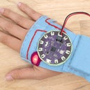

Analog input pins on a microcontroller enable you to gather data from sensors so you can read the world around you. For example, read the bend of an elbow or know how hard someone is pressing on a surface. The data you gather can then be applied to outputs triggering events like an LED fading or a note playing.
In this lesson, you will learn how to build a flex sensor, read a range of values and learn how to manipulate those values in order to control an LED.
You will learn how to:
+ make a flex sensor
+ read sensor values
+ use sensor values to fade an LED
+ smooth sensor values
Step 1: Description + Materials

Download the attached file. It contains the final sketches and patterns for the flex sensor and resistor breakout you will be making in this lesson.
+ microcontroller
+ USB cable
+ alligator leads
+ sewable LED
+ fabric marker
+ flex sensor
+ Velostat (resistive plastic)
+ conductive fabric
+ iron
+ thread
+ needle
+ scissors
+ felt
Attachments

Step 2: The Flex Sensor

Remember the resistor you used to restrict current flow in your sewn circuit? The resistor used in that circuit has a fixed value of resistance that does not change. If current runs through a 47 ohm resistor it will always resist 47 ohms (+/- 5%).
A flex sensor is a kind of sensor where the resistance changes value. In other words, when current is running through it and you bend it the amount of current it resists changes. This gives you a range of values. When the flex sensor is connected to a microcontroller this range of values can be read and used as a way to sense that bending action.
Read Changing Resistance on Multimeter
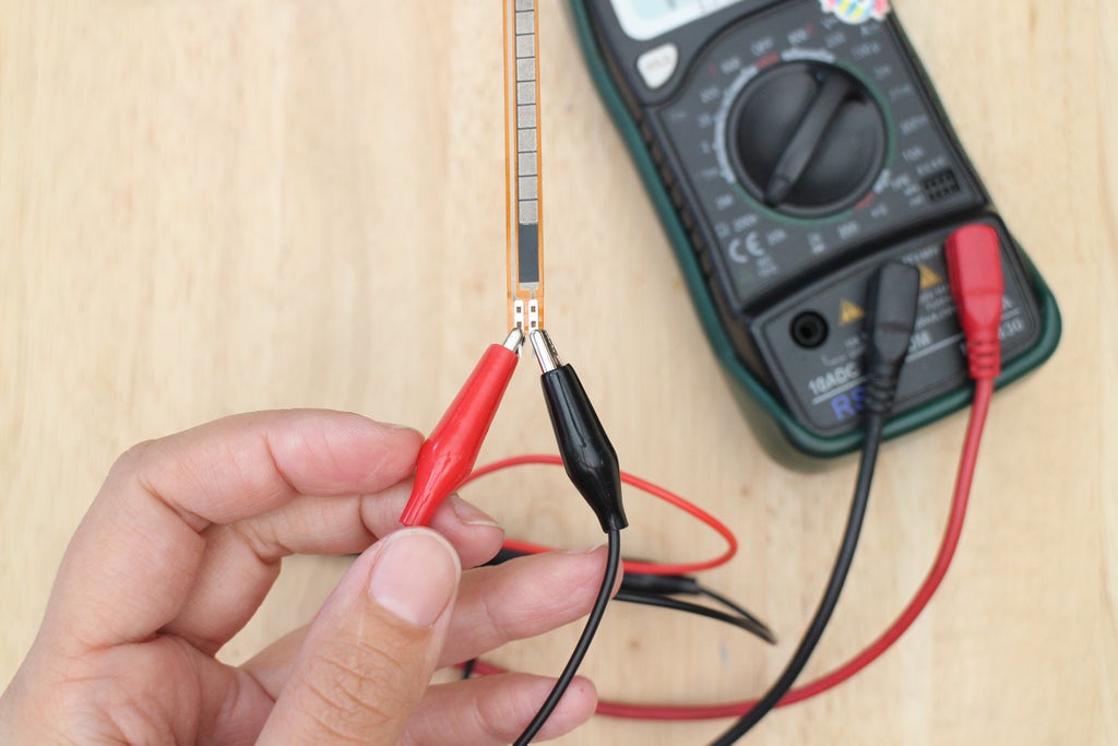
Grab some alligator leads and connect the flex sensor to the red and black probes much like how you connected a fixed sensor to it. The metal leads on the flex sensor are very close together so it may be tricky at first but you will get it eventually!
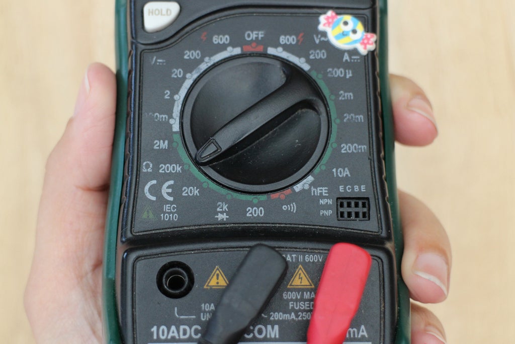
Turn the dial to 200k or any number larger than 20k on your multimeter. A number should pop up on the display screen and tell you that the flex sensor is 10k (or another resistance if you bought a different sensor than the recommended one). Bend the sensor and watch the numbers go up to about 25k. The sensor is changing based on your movements!
Step 3: The Handmade Flex Sensor

Take a good look at the flex sensor. It is a strip of flexible plastic that has a black and metallic design along the length of it. The black is a resistive material and the metallic part is a conductive material. This combination of resistive and conductive material is what makes its resistance change when bent. You can buy conductive and resistive materials that, when put together in the right way, can also make a flex sensor.
The materials you are going to use to make your sensor are conductive fabric and a resistive plastic called Velostat. Velostat changes resistance when force is applied, so it works as a flex sensor but it also works like a force sensing resistor (FSR) which is another resistive sensor. What's cool about a handmade sensor is that you can cut it into any shape you like. They also tend to be a bit more sensitive depending on how it's made.
There is a great instructable on how to make a flex (AKA bend) sensor by Plusea. Head over there and check out her method of making one. You can use any of the techniques and materials she uses to make yours for this class. I will also show you a way to make one in the next steps using the class materials.
Let's make a flex sensor!
Step 4: Cut Velostat

A pattern for a bend sensor is included in the files for this lesson. Use this pattern to cut out all the necessary pieces for your flex sensor. Or, you can design one that is a different shape and size. I will go over step-by-step how to make one without a pattern.
Use a ballpoint pen to draw a rectangle onto the Velostat. This is the pressure-resistive part of your sensor. Once drawn, cut it out using craft scissors.
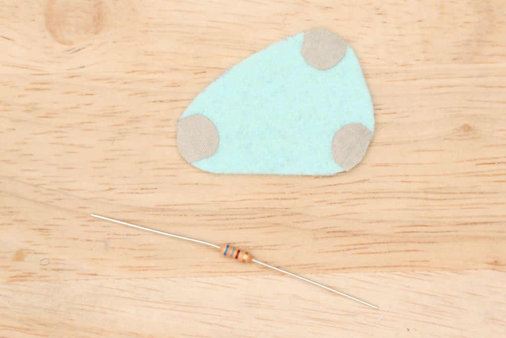
Step 5: Cut Conductive Fabric

You will use conductive fabric to read the changing resistance while electricity is flowing through the plastic. These are similar to the contact design you cut and used for the Hi-5 Collector's soft switch.
Here is the important part - make sure the conductive fabric contacts are small enough to be completely covered by the Velostat. If the contacts touch it will create a short and the electricity will not go through the resistive plastic. You will end up with a soft switch instead of a resistive sensor!
Once you cut out your contacts with leads put them on top of the Velostat and make sure the edges are covered. The lead will poke out of the side which is good.
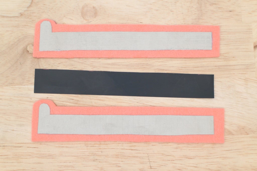
Step 6: Cut Casing and Iron

Place a conductive contact and the resistive rectangle on top of a piece of felt. With your fabric marker draw around the edges leaving a border of at least 1/8".

Cut out two casings from the felt using the same pattern. Place the conductive contacts on top and iron down.
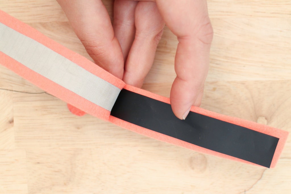
Step 7: Sandwich and Sew

Put the Velostat in between the conductive fabric.

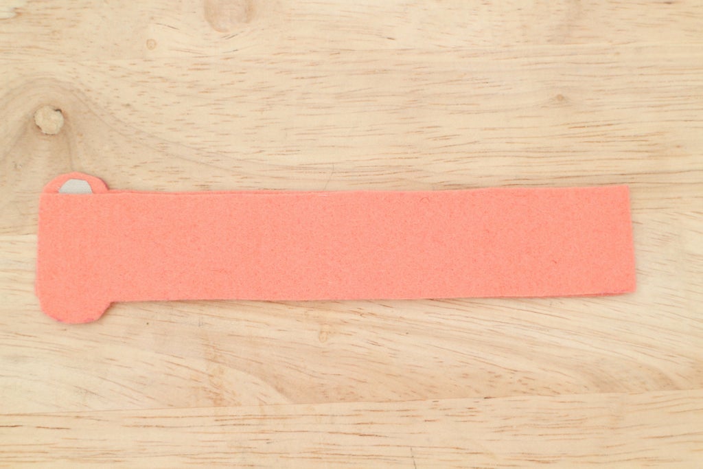
Thread a needle with about 18" of regular thread. Use a running stitch to sew all around the edge of the sensor. Get close to the edge of the Velostat inside but try to avoid piercing through it with your needle. Skip over each conductive fabric lead with the thread rather than sew through it.
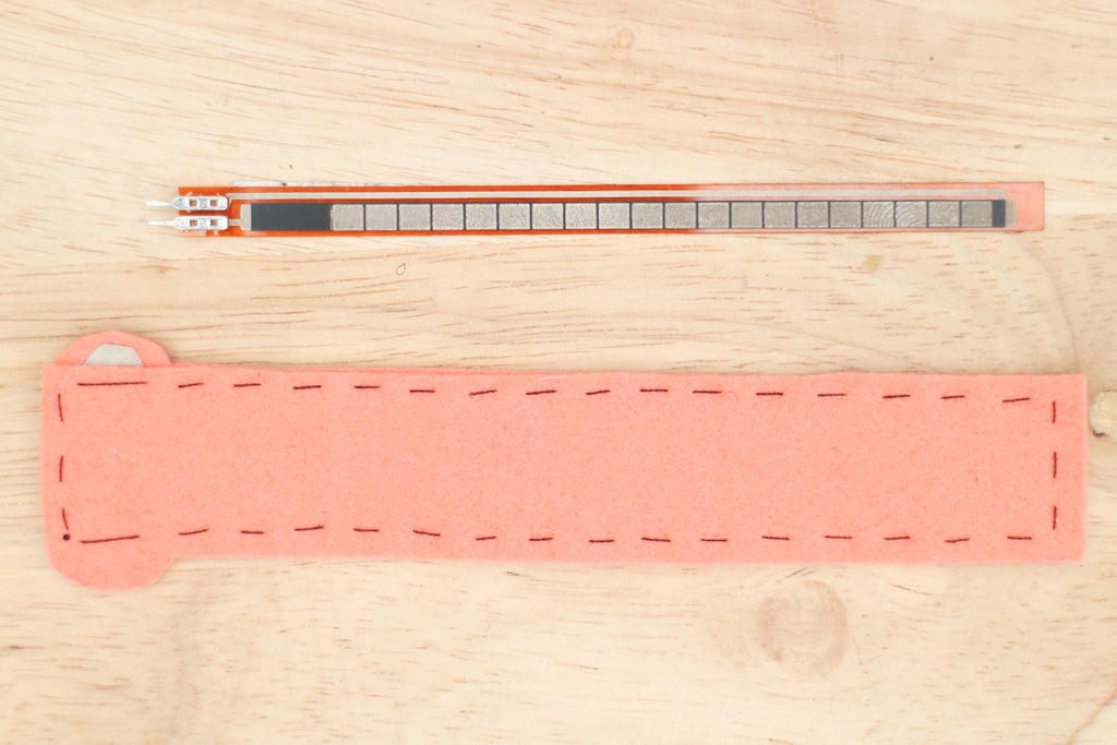
Step 8: Test

Your sensor is done! Time to test it. Connect your handmade sensor to the multimeter. Flip the dial until you get a reading. If you used the provided pattern the resistance of the sensor while it's lying still will be around 1.5k ohms. Press and bend the sensor and watch the resistance go down!
Let the sensor rest and it will rise in resistance to its maximum. Write down this max resistance, you will use it in the next step. My max reading when it is still is 1,200 (1.2k) ohms.
Troubleshooting
The multimeter reads 0.
The metal contacts are touching and creating a short. To double-check turn the multimeter to the continuity setting while the sensor is connected to it. If it beeps you have a short and need to open up the sensor and fix the placement of the Velostat so it covers the two contacts or replace it with a larger piece.
Step 9: Reading Varying Voltage With a Microcontroller
So, how do you get the range of values you see on the multimeter read by a microcontroller? A microcontroller can not read the changing resistance very well like the multimeter, but it can read changing voltage nicely. To translate this range of resistance to a range of voltage a simple circuit is used: a voltage divider circuit.
What is a Voltage Divider Circuit?
To have a microcontroller read a resistive sensor, like your flex sensor, you need a voltage divider circuit. The circuit consists of two resistors. These two resistors can either be two fixed, two variable or one variable and one fixed resistor.
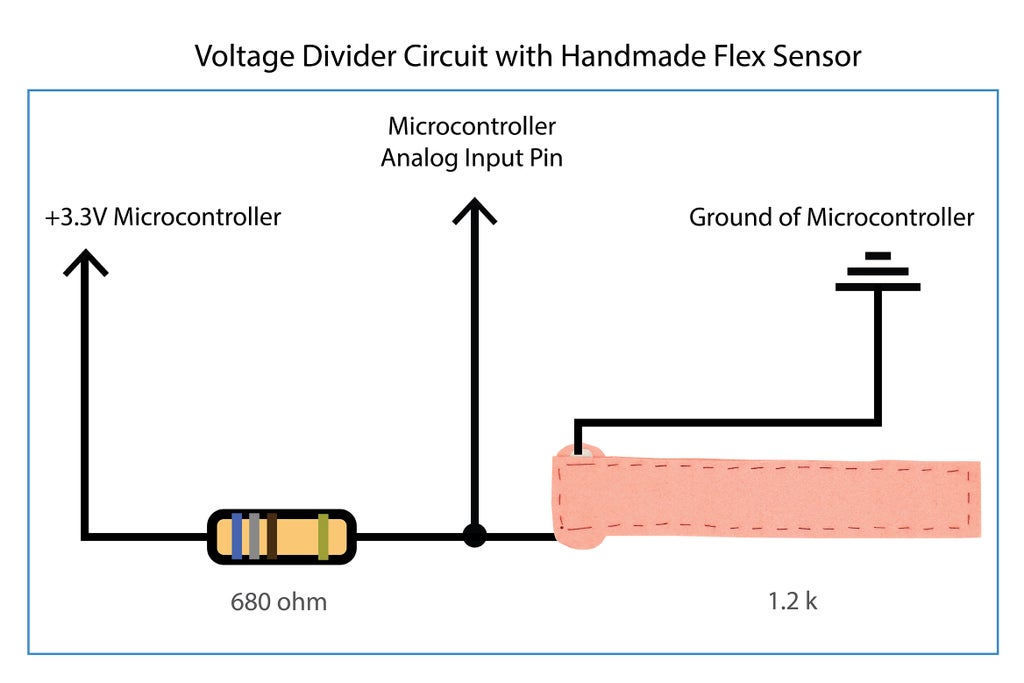
The circuit we are building is the latter with one fixed (like the one you used for the sewn circuit) and one variable resistor you would like to read (the flex sensor!). You run electricity through the two resistors and take a reading from the point where the two resistors meet. When the sensor changes resistance the voltage coming from the middle point, labeled "Voltage Out" in the diagram, changes. Below is the voltage divider circuit using schematic symbols. In this diagram R1 is the fixed resistor and R2 is your sensor (variable resistor).

The value of the fixed resistor (R1) in the circuit is important because it will determine the range of voltage coming out from the "Voltage Out" point.
Choosing Your Fixed Resistor
As you learned in the Introducing Electricity lesson, there are many values of resistors to choose from. We already know R2 represents our sensor in the above diagram. How do we know what value resistor R1 should be? The value of R1 will determine the range of voltage that gets read by the microcontroller, so you shouldn't choose just any value. To get the value that is best for your sensor there is a general rule of thumb to go by. This rule is easy to remember and will ensure you get a nice large range of voltage to work with.
+ Take the max resistance of your sensor and divide it by half. This is the value of your fixed resistor.
For example, the max resistance I measured my sensor at was 1.2k ohms. I divide that by 2 to get the value of the fixed resistor.
1,200 / 2 = 600 ohms
I round up from 600 and will use a 680 ohm resistor for my voltage divider circuit. Divide the max resistance you previously recorded by two and round up to the nearest resistor value you have in your kit. What did you get?
Want to know the math behind this circuit and how it works? I won't get into it here instead, head over to Sparkfun's Voltage Dividers page to learn more and make sure to check out their nifty voltage divider calculator.
Putting it all Together
Ok, so now we have our fixed resistor value which is R1 in the diagram and we have our sensor which is R2. What about the rest of the diagram? What gets connected to what on the LilyPad USB?
Below you can see how the above diagram is applied using your two resistors and the microcontroller. The "Ground" translates to the ground on your LilyPad USB, the "Voltage In" is the 3.3V coming from the power (+) pin on the LilyPad USB and the "Voltage Out" gets connected to an analog input pin so the board can read it changing. The "Voltage In" gets divided so the "Voltage Out" will always be smaller than the "Voltage In".
Great job getting through this! Now, let's get hands-on and see how this works. In the next few steps, we will connect the sensor to the board and read some values!
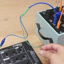
Step 10: Build Circuit

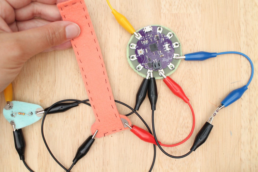
Let's read the sensor's values and add an LED as an output. This next exercise uses the sensor to fade on and off an LED. Grab your trusty alligator leads and make these connections:
flex sensor --> power (+) LilyPad
flex sensor --> resistor
resistor (same side the flex is connected to) --> pin A2 LilyPad
resistor --> ground (-) LilyPad
LED power (+) --> pin 3 LilyPad
LED ground (-) --> ground (-) LilyPad
Connecting to the Resistor
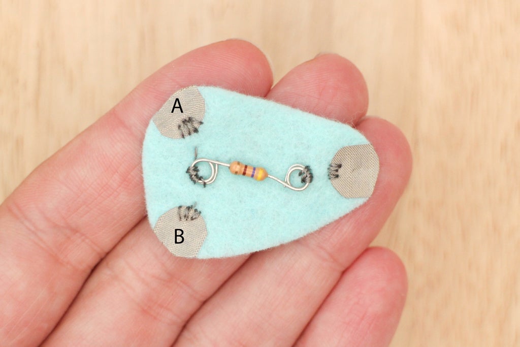
You may have noticed that my 680 ohm resistor is looking a bit different. One lead of the resistor gets two connections: one to the sensor and the other to pin A2.

To make it easier to clip to I sewed the resistor to a piece of felt and to three conductive fabric pads. You do not have to make this but if you would like to, there is a pattern included in this lesson's files. Here is how you make it!

Cut out felt.

Cut small squares of iron-on conductive fabric.
Iron on the fabric tabs.
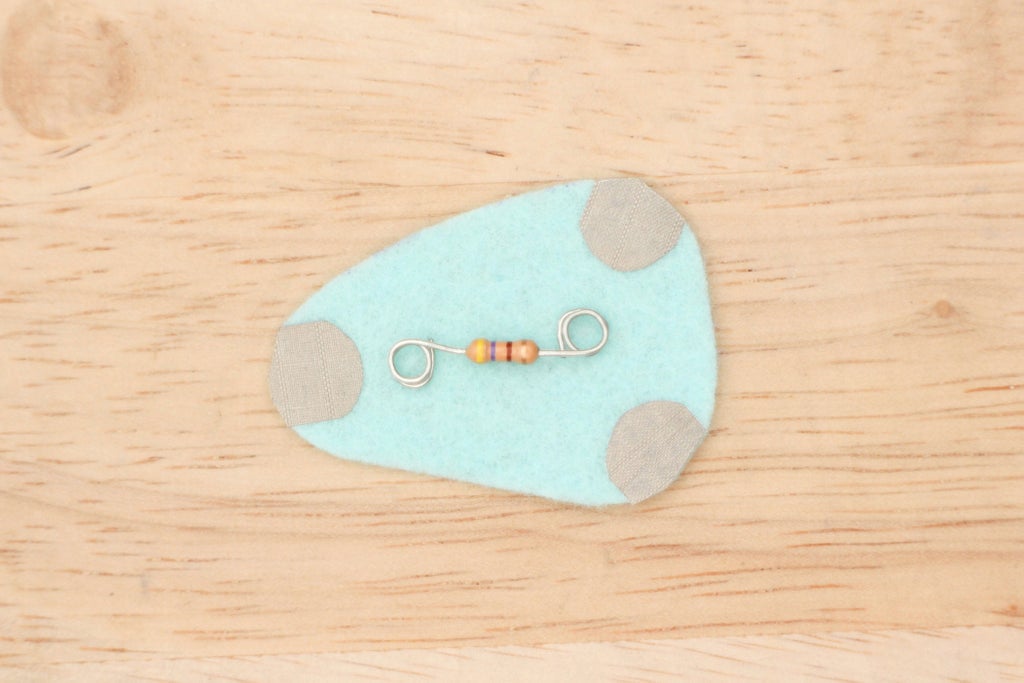
Curl up resistor leads.
Using conductive thread, sew one lead of the resistor to the two pads labeled A and B and the other lead to the remaining one. Use this to prototype with and in your final project if you like!
Step 11: Open Sketch

In Arduino navigate to:
File > Examples > Analog > AnalogInOutSerial
Copy, paste and save sketch as flexLED.
Step 12: Upload

Change the pin numbers in the first two lines of code.
analogInPin is the pin your sensor is connected to.
analogOutPin is the pin your LED is connected to.
const int analogInPin = A2;
const int analogOutPin = 3;
Upload sketch and bend the sensor to change the LED's brightness.

Step 13: Get Max and Min

Open the serial monitor to see the sensor's values.
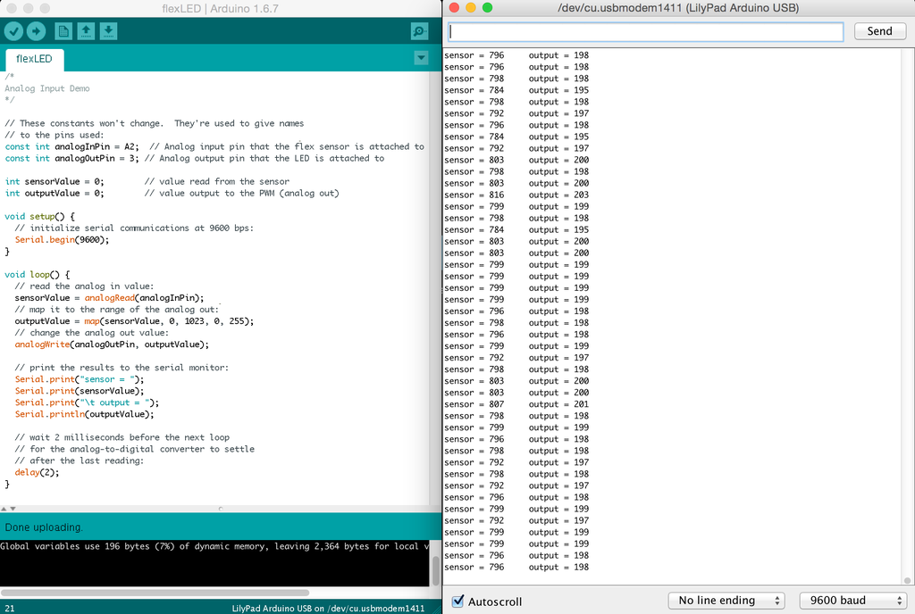
Take a look at the numbers next to "sensor =". When the sensor is resting record the number you see here. The number will change constantly so record the one you see the most and round to the nearest ten. Mine is:
780
Now, bend or press it to the maximum amount and record that number to the nearest ten. Mine is:
1020
Hang on to these numbers, you will plug them into your sketch in a next step.
Step 14: The Code

Let's go over what the code is doing in this sketch. Some of this may start to look familiar to you.
Declare two variables that hold the pin numbers the flex sensor and LED are attached to.
const int analogInPin = A2;
const int analogOutPin = 3;
Create a variable to hold the sensor's values coming in and one for the value that will be sent out of pin 3.
int sensorValue = 0;
int outputValue = 0;
Open serial port.
Serial.begin(9600);
AnalogRead()
Read the sensor by calling analogRead() and passing in the analogInPin variable. This function reads an analog value from an analog pin that is connected to a 10-bit analog to digital converter. This means that when you print sensor values to a serial window, the range you will see will be 0 - 1023.
sensorValue = analogRead(analogInPin);
Map()
The map() function maps a range of values to another range of values. This is useful for mapping sensor values to the brightness of an LED. When reading an analog value (like reading the flex sensor) the range is from 0 - 1023. When writing an analog value (like writing to an LED) the range is from 0 - 255.
The input range gets scaled to the output range using map() and the new range gets put into a variable called outputValue. The map() function has five arguments, these are the values in order: the value you are changing, old minimum, old maximum, new minimum, new maximum.
outputValue = map(sensorValue, 0, 1023, 0, 255);
Write the newly mapped output value of 0 - 255 to the pin our LED is on.
analogWrite(analogOutPin, outputValue);
Serial print the phrase "sensor = ".
Serial.print("sensor = ");Print the sensor value before it is mapped.
Serial.print(sensorValue);
Tab over and print the phrase "output = ".
Serial.print("\t output = "); Print the newly mapped value that is the final output sent to the LED.
Serial.println(outputValue);
When you open the serial monitor, you will see the sensor values streaming. The column on the left are the raw, unmapped values, the column on the right are the mapped values your LED is receiving.
Step 15: Change Sensor Range
This is where you plug in the max and min values you recorded in the previous step. Mine were 780 and 1020. Plug your minimum where it says 0 and your maximum where it says 1023 in the map() function in the flexLED sketch.
outputValue = map(sensorValue, 0, 1023, 0, 255);
Here is what the line of code looks like with my values.
outputValue = map(sensorValue, 780, 1020, 0, 255);
Put your values in and upload the sketch again. The LED will now have a larger fade range because it is calibrated to your sensor. If your LED flickers it means that you should raise or lower your minimum and maximum. For example, if your sensor drops below the minimum you put in the sketch the board will give the LED full voltage and it will get very bright. You can also see this happen in the serial monitor, the values next to "output =" will become negative. If this happens lower the minimum in your sketch.
Step 16: Smoothing Sensor Values
Sometimes sensor values can be a little unreliable, which can cause unreliable behavior from your output. Open the serial monitor and take a good look at the sensor values as you interact with the flex sensor. Even when it's seemingly still the values jump anywhere within 50 values, that's a lot! Ideally, you want to minimize the noise and narrow down that window of jumpy values.
To help with this, math can be done to average or smooth out the sensor values. The newly averaged values are the ones that go to your LED, which means a smoother LED fade too!
Step 17: Open + Upload Sketch With Smoothing

Open the flexLEDsmooth sketch you downloaded at the beginning of this lesson. This sketch is using the smoothing code from the example sketch you can find in Arduino by navigating to: File > Example > Analog > Smoothing.
Hit upload and open the serial monitor to see the new, improved and smoothed values of the sensor and its mapped output. The fade of the LED will appear to be smoother too!
Step 18: The Code
Let's go over the new parts of this sketch that average the sensor values to make those nice smooth new values. Make sure to read the comments in the sketch too, which are already very informative.
Make a variable and put in it the number of readings you want to average. To get a range smoother, experiment by raising this number. For example, try taking 20 readings instead of 10.
const int numReadings = 10;
Declare an array named readings that will hold these 10 readings. An array is able to contain multiple values at once instead of just one like a variable.
int readings[numReadings]; // the readings from the analog input
Create variables to hold values for smoothing.
int readIndex = 0;              // the index of the current reading
int total = 0;                  // the running total
int average = 0;                // the average
This for statement sets all the spots in the array to 0. This only happens once in the beginning of the sketch.
for (int thisReading = 0; thisReading < numReadings; thisReading++) {
readings[thisReading] = 0;
}
Populate the array with sensor readings.
total = total - readings[readIndex];
readings[readIndex] = analogRead(analogInPin);
total = total + readings[readIndex];
readIndex = readIndex + 1;
if (readIndex >= numReadings) {
    readIndex = 0;   }
Average the sensor readings and put the new smoothed values in a variable called average.
average = total / numReadings;
Step 19: Test Your Knowledge
{
    "id": "quiz-1",
    "question": "When making a flex sensor by hand the metal contacts should touch each other.",
    "answers": [
        {
            "title": "True",
            "correct": false
        },
        {
            "title": "False",
            "correct": true
        }
    ],
    "correctNotice": "That's correct",
    "incorrectNotice": "That's incorrect"
}
{
    "id": "quiz-2",
    "question": "In order for a microcontroller to read a resistive sensor you need a voltage divider circuit.",
    "answers": [
        {
            "title": "True",
            "correct": true
        },
        {
            "title": "False",
            "correct": false
        }
    ],
    "correctNotice": "That's correct",
    "incorrectNotice": "That's incorrect"
}
{
    "id": "quiz-3",
    "question": "A sensor’s values can be smoothed by taking a number of readings and averaging them.",
    "answers": [
        {
            "title": "True",
            "correct": true
        },
        {
            "title": "False",
            "correct": false
        }
    ],
    "correctNotice": "That's correct",
    "incorrectNotice": "That's incorrect"
}
{
    "id": "quiz-4",
    "question": "To scale the range of a sensor’s values from 0 - 1023 to 0 - 255 you use this function.",
    "answers": [
        {
            "title": "average()",
            "correct": false
        },
        {
            "title": "analogRead()",
            "correct": false
        },
        {
            "title": "map()",
            "correct": true
        }
    ],
    "correctNotice": "That's correct",
    "incorrectNotice": "That's incorrect"
}
Step 20: All the Sensors

You now know how to read a sensor, map its range and smooth its values. You can read and map other variable resistor sensors in the same way, such as a photocell (light sensor), force sensing resistor (FSR) and potentiometer. In the next couple of lessons, you will apply these new skills and learn how to use your handmade sensor to sense body movements.
Upload a photo of your circuit using the final flexLEDsmooth sketch below! Include any process shots you took along the way.


