

Introduction: Diodes


Of all of the components — in my mind at least — diodes sound the most futuristic. Even the parts of the diode — cathode and anode — sound like they have come directly out of a science fiction novel. However, you don't need a time machine to experience the full glory of diodes. Like all of the other components we have visited so far, diodes are everywhere. Except, unlike most of them, you actually see diodes all of the time. If you did not already know, LED stands for light emitting diode. Any time you see an LED display, you are looking at a diode in action. Although, not every diode lights up, they all do work roughly the same way. Let's take a moment and learn about what diodes actually are.
Step 1: What Is a Diode?

A diode is an electronic component that allows electricity to flow through in one direction, and all but stops it from flowing the opposite way.
Unlike other electrical components we have looked at thus far, whose primary role is to influence the voltage or current within the circuit,
the diode's primary role is to route electricity. This is extremely
useful for preventing an electrical signal from taking unwanted or
unexpected routes within the circuit.

Like an electrolytic capacitor, all diodes are polarized. This means they have an anode (positive side) and cathode (negative side). You can tell the difference because the cathode has a little line painted around it.

In a schematic, diodes look like arrows pointing at a wall. A good way to think of this is that a positive voltage can flow in the direction of the arrow, but the wall stops it from flowing back the other way.
Step 2: How Diodes Work

A diode consists of a PN junction made of P-type silicon and N-type silicon separated by a depletion region. The depletion region acts like an insulator. Put simply, the P-region is connected to the anode, and the N-region is connected to the cathode. The depletion region sits between the two.

When the P-region is connected to ground and the N-region is connected to a positive voltage, the depletion region actually grows in size instead of shrinking. This ensures little to no electricity is able to flow through the diode between power and ground. In this configuration the diode is called reverse biased.

When a positive voltage is applied to the P-region and the N-region is connected to ground, the depletion region all but disappears and allows electricity to flow. In this state the diode is called forward biased.

In order to overcome the depletion region, a little bit of voltage must be sacrificed. This is called the voltage drop. In a standard silicon diode this is typically 0.7V. In
other words, if you have a 5V signal and it passes through a diode with
a 0.7V drop, the voltage that comes out the other end will be 4.3V. It can fluctuate above or below this value depending on the type of diode.
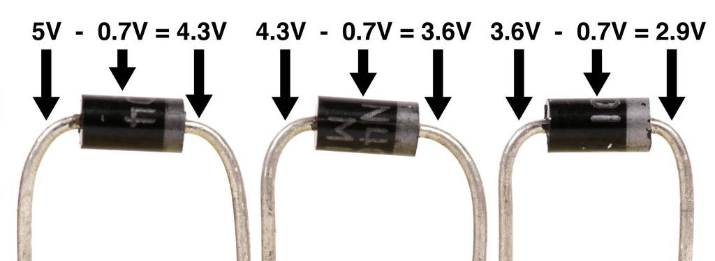
If
you have three diodes in series, you will lose 0.7V through each diode
and the voltage at the far end of this chain will be 2.9V. This adds up to a
significant loss, and is the reason diodes should be used sparingly.

While diodes charge a toll to cross the depletion region in the form of voltage, they offer no real resistance. If you put only diodes in a circuit without a load to use up the electricity, it will virtually look like a short circuit and draw as much current as the power supply is able to provide. Since that is likely higher than the diode's maximum current rating, it will release the diode's magic smoke.
Step 3: Deciphering Diodes

There isn't too much to know about reading diodes. Typically, the name of the diode is printed right on it. The name is its part number, and has nothing to do with the actual value of the component.
Sometimes the name is printed horizontally across the body which makes it very easy to read.

Sometimes it is printed around the circumference which makes it extremely annoying to read, especially since they tend to be small-ish.
Step 4: Special Diodes
While diodes by and large all do the same thing, there are certain diodes that perform specialized functions.

Schottky diodes are very similar to standard signal diodes, but have a very low forward voltage - as little as 0.2V - and a really fast switching action. They are good in applications in which the diode needs to work very rapidly, and/or a minimal amount of voltage loss is required.

Zener diodes work like normal diodes. However, when a really large voltage is applied to a reverse-biased zener diode, the aptly named Zener Effect kicks in and allows a fixed amount of electricity to flow the 'wrong way' through the diode. This makes this diode useful as a crude voltage regulator in low-current applications.

Lastly, the one diode that really shines above the others is the LED.
Step 5: The LED

LED is an abbreviation for light emitting diode. Of all of the electronic components we are going to encounter in this course, the LED gets the most fanfare. It is the superstar of electronic components. You could say it shines brighter than the rest.

An LED is a diode that emits photons when it is forward biased and there is electricity flowing through it. The photons are simply light particles and what makes it glow.

If you look very carefully inside of an LED you will see a thin wire attached to the center of a small bowl. The wire bridges the anode and cathode to a semiconductor die located at the bottom of the reflective bowl. When current flows from the anode to the cathode, the semiconductor material emits photons, reflects off the bowl, and is further amplified by the plastic material of the cap.
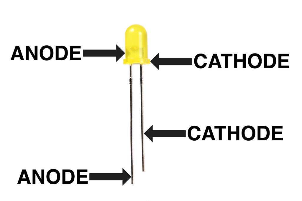
There are typically three ways to tell a standard 5mm LED's anode from its cathode.
1) The leg connected to the anode is typically longer than the one connected to the cathode.
2) The body of the LED typically has a flat spot on the cathode side.
3) If you look inside the LED, the little metal bit connected to the anode lead is much smaller than the cathode.
Step 6: Current Limiting Resistors

Since an LED offers no resistance in a circuit, it typically requires a current limiting resistor in series with it.

This prevents the LED from being shorted and - given enough current - literally exploding.

As a general rule of thumb, a 470 ohm resistor should be more than enough to protect just about any low power LED.

However, should you want to calculate the proper resistor for maximizing brightness, you can calculate this by using this equation. Even more simply, you can search online for "LED resistor calculator."

For instance, given this LED with a 3v forward voltage, 20mA operating current, and a 9V source, we can calculate that the proper resistance is 300 ohms. However, that is the absolute minimum resistor, and since resistors tend to have a tolerance range, it is best to increase the value a little to be on the safe side. It is safe to say then that a 330 ohm resistor should do the job. However, you don't want to increase it too much because the more resistance there is, the dimmer the LED becomes.
Step 7: LED Bonanza
There are so many different types and form factors of LEDs at this point, it is hard to keep up.

LEDs come in different shapes and sizes. The 5mm domed is the most common, but you are likely to also find them in 3mm domed, 10mm domed, rectangle, oval, and square (to name a few).

LEDs also come in many different colors. Often the plastic is tinted to indicate what color they are. However, clear LEDs are deceptive in that you might assume they glow white, but can actually glow a host of different colors.

LEDs have different levels of brightness that are typically measured in MCD (millicandella). One thousand millicandella is equivalent to the brightness of one candle. So, an LED like the one pictured above with an intensity of 6,000mcd is equal to the brightness of 6 candles. It is not uncommon to also see extremely bright high-power LEDs to be measured in Lumens - another unit of light measurement - or Watts.

LEDs have different viewing angles, or beam widths. What this means is that the visible brightness of the LED seems to decrease when you are looking at the LED from and a spot outside of its ideal viewing angle. This angle also determines the size of the spotlight created by the LED. Viewing angles on LEDs can vary widely.

LEDs also draw different amounts of power. In fact, some high power LEDs draw so much power that they are mounted on metal heatsinks to dissipate heat. While LEDs such as these tend to be very bright, they sometimes require special circuitry to drive them.

LEDs can come grouped together into display modules. With these LED dot, bar, and 7-segment numerical displays, each individual light-up segment is a discrete LED. For instance, the 8X8 matrix on the left actually has 64 separate LEDs inside of it.

LEDs also come packaged in flexible strips. These strips are manufactured in white, solid colors, and multi-color, which can produce any color in the visible spectrum. Additionally, the multi-color strips either come in solid colors, or in programmable arrays where each LED can be a different color. Learning how to control programmable LED strips is beyond the scope of this class, but something you can do if you ever decide to learn how to use a microcontroller such as an Arduino.
In short, there are a lot of ways you may encounter LEDs. If you want to know more about LEDs, check out my LED and Lighting course!


