

Introduction: Haas Mill Workholding Templates


In this lesson, you will learn the steps for setting up a CAM file in Fusion 360 for the Haas Mill. Then, you will learn how to prepare the machine to run your programs.
1) Open Fusion 360 and navigate to the CNC at Pier 9 Team Hub.
Here is an introduction to the Haas Mill template file structure:
Recap:
--There are three receiver plates inside the Haas Mill that are never removed.
--You may choose a fixture plate, one vise, or multiple vises.
--If you choose one vise, you may choose between the Small, Medium, or Large Lang for rectangular stock, or the 3-Jaw Chuck for cylindrical stock.
--If you choose multiple vises (two or three), you can have one piece of stock spanning two or three vises, or three pieces of stock in three vises. The naming convention is: #ofStockPieces_#ofVise(s)_ViseType_JawOrientation_PartOrientation
2) Bring your part into the template file using the steps in the video:
Recap:
--Navigate to the template file. Double click to open it.
--Drag part from Data Panel into active window.
--Move part until it's visible from all sides, then hit Enter.
Note that once you bring your part into the assembly file as a Component, Fusion creates an automatic link between the part and the assembly. This means that if you modify your model in the original part file, these changes will also appear in the assembly file. If you do not want your part to be linked, you can break the link by right-clicking the part and choosing Break Link.
3) Save the file under a new name using these steps:
Recap:
--Under File, choose Save As.
--Save in the Master Folder under new name.
4) Create a joint between your stock and your part using these steps:
Recap:
--Use hotkey J to create a joint.
--For Component 1, click on the center bottom (or top) of your part.
--For Component 2, click on the center bottom (or top) of the stock.
--Flip joint around if necessary. Add an offset if you've joined the center top of the part and stock, to leave room for facing.
--Joint type should be Rigid. Click OK.
5) Edit the stock dimensions using the steps in this video:
Recap:
--In the Modify dropdown, choose Change Parameters.
--Under Favorites, change the stock dimensions and extrusion. Click OK.
Step 1: Haas Mill CAM Setup
Now you're ready for CAM, Computer Aided Manufacturing.
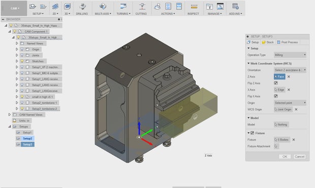
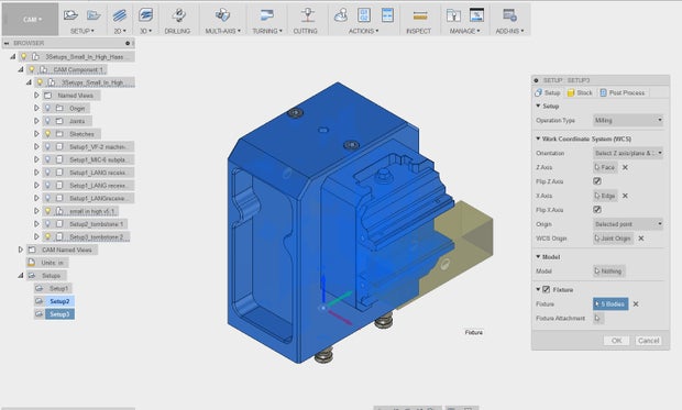
1) Edit Setup 1 to check the Work Coordinate System, select the Model body, and verify the Fixture:
Recap:
--Right click Setup 1.
--Verify that the Work Coordinate System is set to the center top of the receiver plate.
--Click Nothing next to Model. Then select the part. If you are having trouble selecting the model, expand the browser tree on the left and turn off the visibility of the stock (under Bodies).
--Click 12 Bodies next to Fixture. Verify that the Haas subplate, receiver plates, and vise(s) are all selected as the fixture.
2) Continue editing Setup 1 to verify the stock and set the Work Coordinate System Offset to 7:
Recap:
--In the Setup dialogue, click the Stock tab.
--Verify that the Stock Solid body is correct.
--Click the Post Process tab.
--Change the program number to a four-digit integer.
--Change the WCS Offset to 7.
This changes the active WCS from G54 to G154 P1.
--Click OK to create Setup 1.
Step 2: Haas Mill Post Processing
You have now set up your template file.
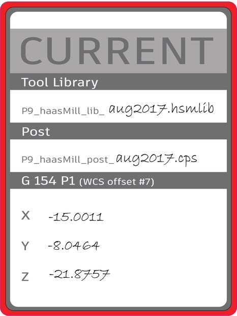
1) Before starting CAM, confirm that you are using the latest Haas Mill tool library, labeled on the sticker outside the machine and available for download in the Pier 9 CNC Data Instructable.
The naming convention is: P9_haasMill_lib_MonthYear.hsmlib
2) Finish your CAM toolpaths, simulating as you go.
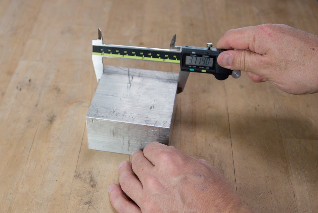
3) After you are done with CAM and all toolpaths are verified, cut your stock.Take measurements with a caliper and update your CAM Setups.
This is especially critical because you will be skipping the step of setting G54 by probing the back left corner of the stock (or wherever the WCS is set). If your stock dimensions are inaccurate, you could unintentionally put too much load on a tool.
4) When you are ready to post process, double check that you are using the latest Haas Mill post processor, linked in the Pier 9 CNC Data Instructable.
The naming convention is: P9_haasMill_post_MonthYear.cps
5) Write a description comment, and then post your code to a USB drive.
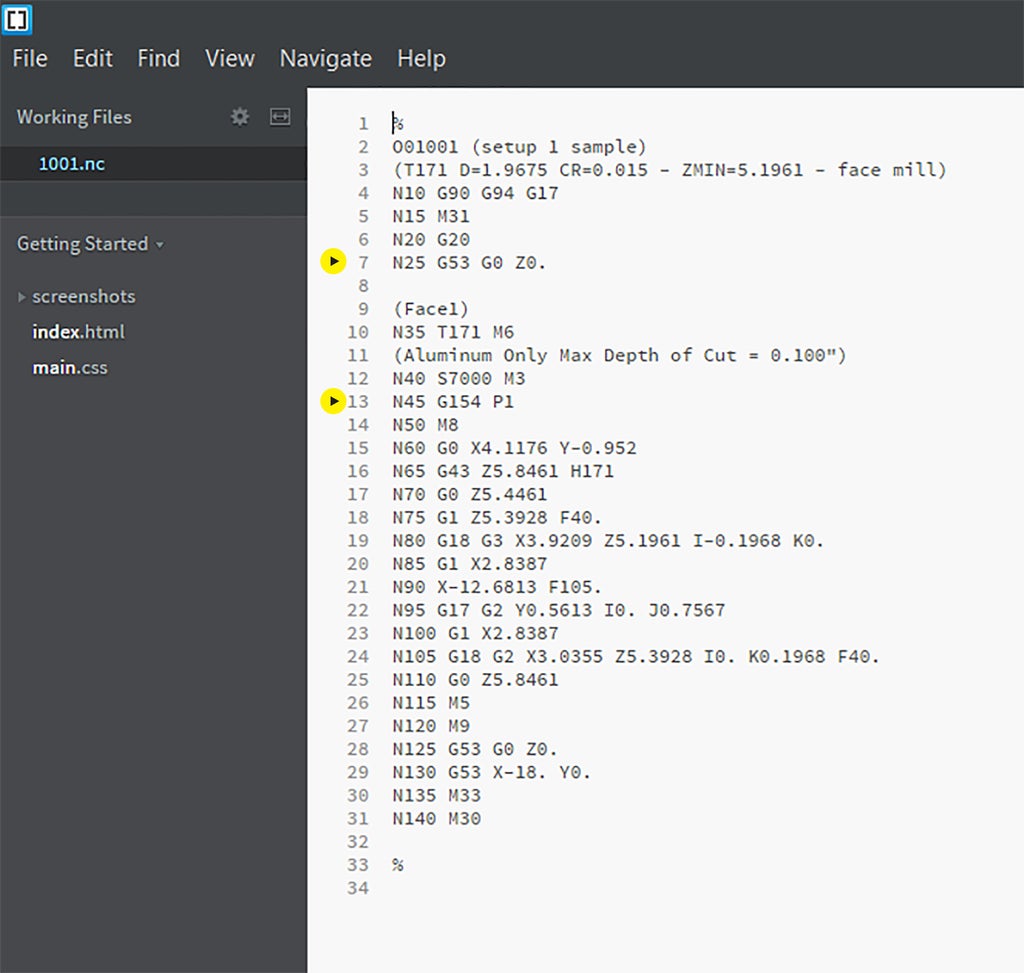
6) In the editor, verify that after the first tool change, your code calls out G154 P1.
Using Ctrl + F, the Find command, can be useful when searching through G-code. Remember that G53, in the code header, specifies the Machine Coordinate System. G154 P1 is the Work Coordinate System.
Step 3: From Software to Hardware
Now that you've posted your G-code, it's time to move into the CNC shop. The subsequent steps in this lesson take place at the Haas Mill. You'll learn how to install the fixture plate for large or flat stock, install vises and stock, use the tombstone, and install the Kurt vise system.
Step 4: Installing the Fixture Plate
If you plan to work with very large, flat, or irregularly shaped stock, the Haas Mill fixture plate is a versatile system to use.
This plate features two sets of holes, 1/2"-13 and 1/4"-20, at 2" intervals, center to center. You can use the 1/2"-13 holes with step clamps to hold down your stock. Alternatively, you can use either set of holes with countersunk bolts in through-holes in the stock itself.
The model of this plate appears under p9 Workholding/Haas VF2/Fixture Plate.
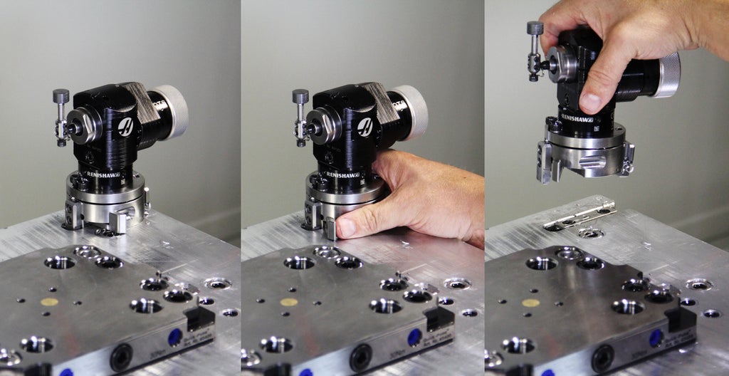
1) Remove the Optical Tool Setter (OTS).
Push the lever at the base away from you, and lift.
2) Clean the three receiver plates and bottom of the fixture plate with a dry cloth to remove chips and debris.
Any chips trapped between the two can damage the receiver plates, and can cause tolerances to decrease over time.
If necessary, remove blue hole plugs on the far and right sides of the receiver plates by cupping your hand and using compressed air. For holes you will not need, replace blue hole plugs to prevent chips from getting inside the receiver.
3) Install fixture plate by placing clamping studs on the bottom of the plate inside the holes in the receiver plates.
Ensure FRONT is facing forward.

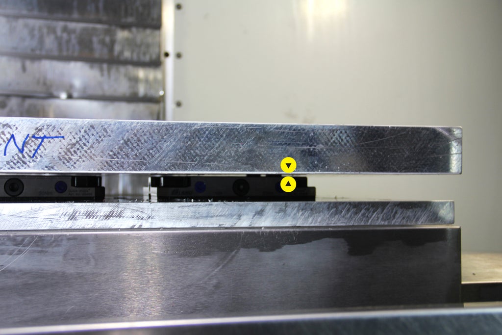
4) Use a mallet to ensure that the fixture plate seats properly.
Notice the gap in the image below. This would prevent the subplate from being square to the machine.

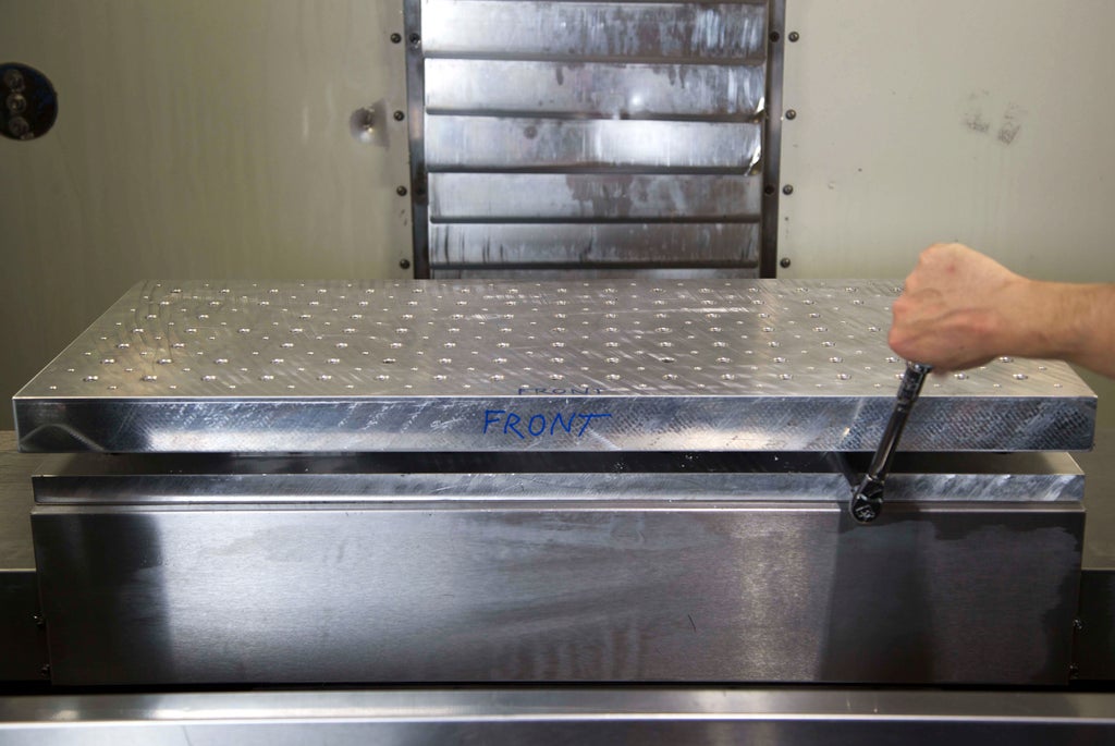
5) Secure the fixture plate to the right and left receiver plates.
Use an 8 mm allen driver on the blue handled torque wrench set to 30 N m. Review Lesson 2 for a reminder on how to set torque levels.
Tighten until the wrench disengages with a clicking sound.
6) Clamp your stock.
Use 1/2"-13 step clamps or countersunk through-holes in the stock with either 1/2"-13 or 1/4"-20 bolts.
If using step clamps, verify that the clearance and retract heights in your CAM program are high enough to prevent collisions. Unless you modeled your own workholding system, your collision detection will be inaccurate.
Do not machine further than 0.02" below the top surface of the fixture plate.
Once you are finished with your operations, check to see if you've significantly impacted the flatness of the top surface. If you have, please face it flat again.

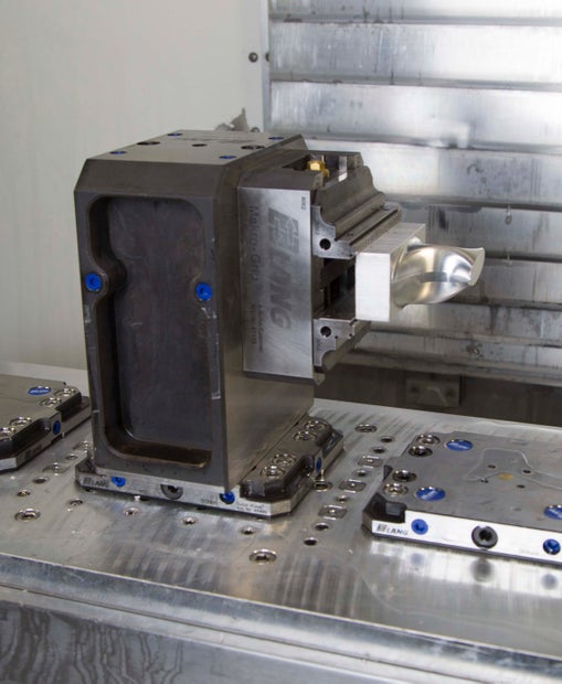
Step 5: Installing a Lang Vise
If you are using a single Makro Lang vise with rectangular stock up to 8-10" along the X-axis, here are the steps for installing the vise and securing your stock.
1) Clean the receiver plate and vise with a dry cloth to remove chips and debris.
Any chips trapped between the two can damage the vise and receiver plate, and can cause tolerances to decrease over time.
If necessary, remove blue hole plugs by cupping your hand and using compressed air. For holes you will not need, replace blue hole plugs to prevent chips from getting inside the receiver.
2) Ensure the 8 mm allen bolt in the front of the receiver plate has been turned counterclockwise enough to allow the vise to sit flat on the plate.
3) Install vise by placing clamping studs in the bottom of the vise inside the holes in the receiver plate.
Ensure the front of the vise is facing you. The front jaw will have the letter L, indicating that the threaded rod that closes the jaws will tighten the jaws when turned clockwise. The front jaw will also indicate the maximum torque, 100 N m
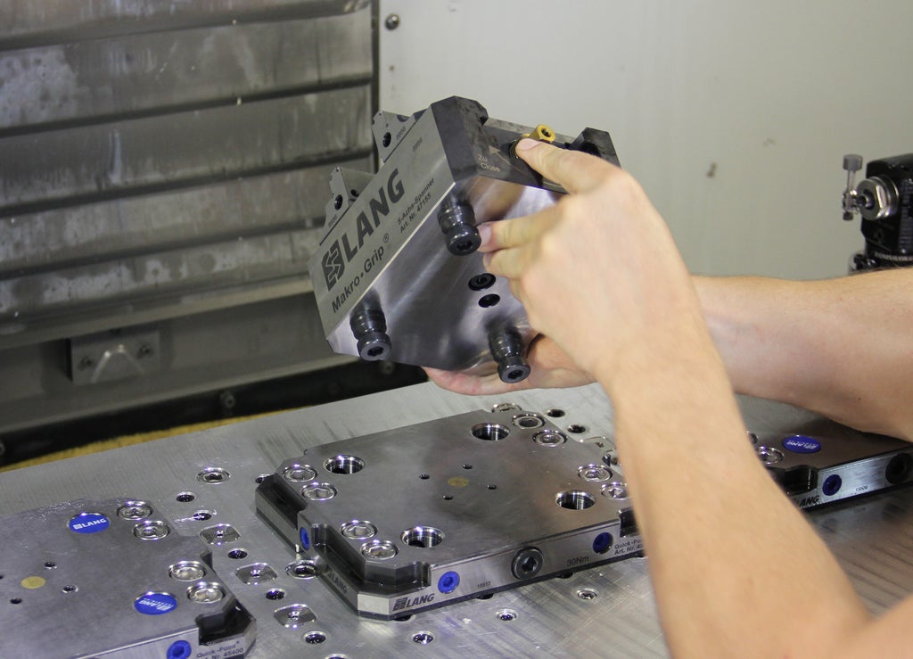
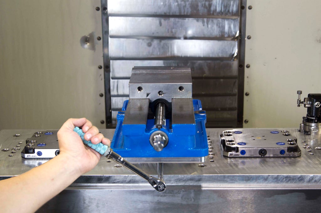
4) Secure the vise to the receiver plate.
Use an 8 mm allen driver on the blue handled torque wrench set to 30 N m. Review Lesson 2 for a reminder on how to set torque levels.
Tighten until the wrench disengages with a clicking sound.
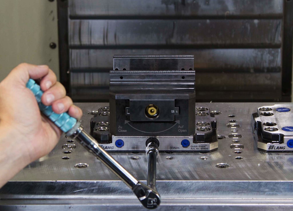
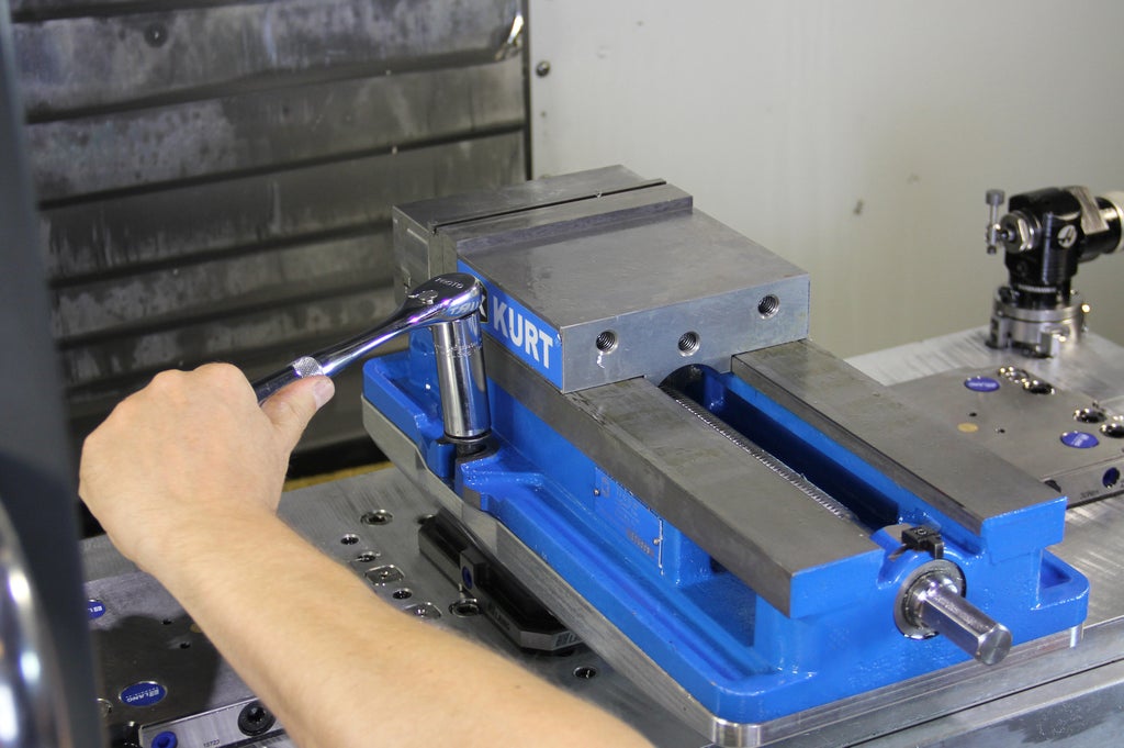
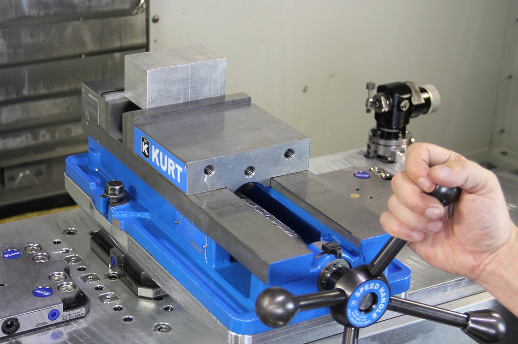
5) Install stock in vise.
Center the stock in the vise jaws with the tick marks along the jaws. If needed, use calipers.
Use the 12 mm socket on the black handled large torque wrench, set to 100 N m.
Tighten until the wrench disengages with a clicking sound.


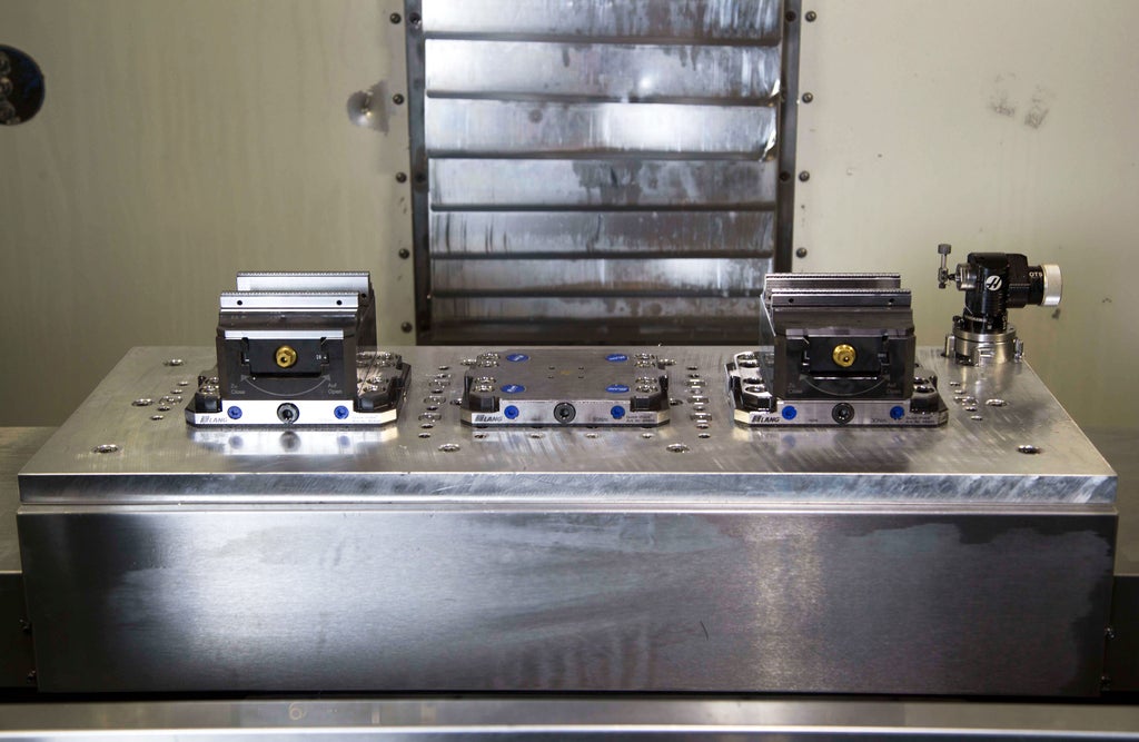
Step 6: Using Multiple Lang Vises
If your program requires multiple Lang Vises, follow these steps.
You'll use two vises side-by-side for stock up to 14-18" along the X axis.
You'll use three vises, or two vises on the right and left side, for stock between 20-29" along the X axis. Note that 30" is the full travel distance of the Haas table along this axis.
1) Install the vises onto the receiver plates following the steps in the previous section.
Use an 8 mm allen driver on the blue handled torque wrench set to 30 N m. Review Lesson 2 for a reminder on how to set torque levels.
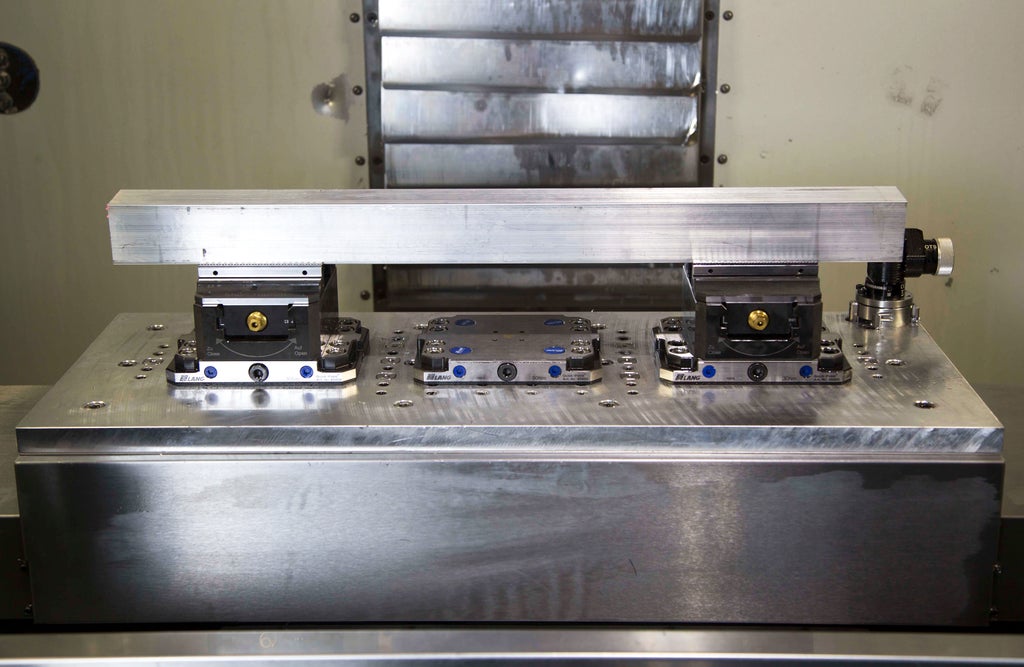
2) Install stock inside the vise jaws.
If you are using one piece of stock across multiple vises, ensure that it is centered with calipers.
Tighten multiple vises hand-tight, then go back and forth between vises, slowly increasing torque each time with the 12 mm socket on the black handled large torque wrench, set to 100 N m.
When the wrench disengages with a clicking sound on one vise, make sure to re-set it before tightening down the next vise.
Continue this process until all vises have been tightened to 100 N m and the stock is fully secured.
Step 7: Using the 3-Jaw Chuck
If you are using cylindrical stock up to 7 " in diameter with the 3-jaw chuck, follow these steps for installing the chuck and securing your stock.
1) Clean the receiver plate and chuck with a dry cloth to remove chips and debris.
If necessary, remove blue hole plugs by cupping your hand and using compressed air.
For holes you will not need, replace blue hole plugs to prevent chips from getting inside the receiver.
2) Ensure the 8 mm allen bolt in the front of the receiver plate has been turned counterclockwise enough to allow the chuck to sit flat on the plate.
3) Install chuck by placing clamping studs in the bottom of the chuck inside the holes in the receiver plate.
Ensure the front of the chuck is facing you. The 10.9 mm square socket should be slightly left of center.

4) Secure the chuck to the receiver plate.
Use an 8 mm allen driver on the blue handled torque wrench set to 30 N m. Review Lesson 2 for a reminder on how to set torque levels. Tighten until the wrench disengages with a clicking sound.

5) Install stock in chuck.
Center the cylindrical stock in the chuck jaws and place in the high or low position.
Use a 10.9 mm square driver on the large black handled torque wrench set to 70 N m.
Tighten until the wrench disengages with a clicking sound.
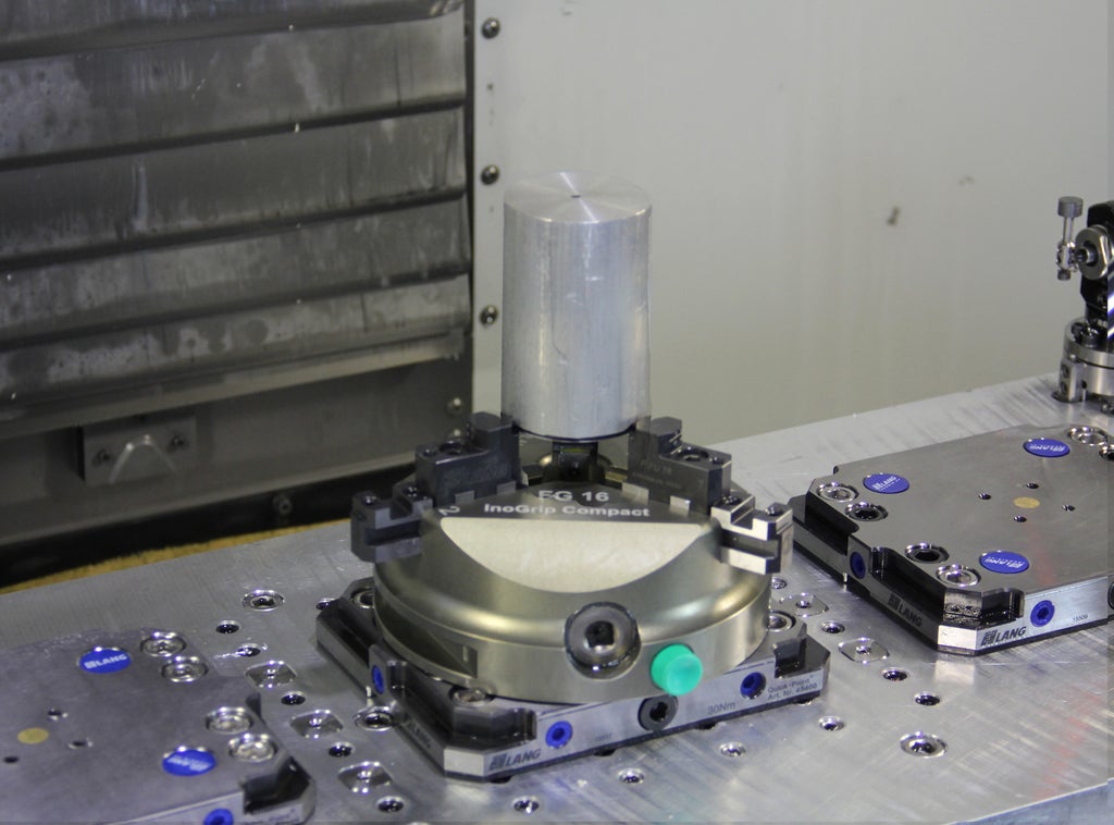
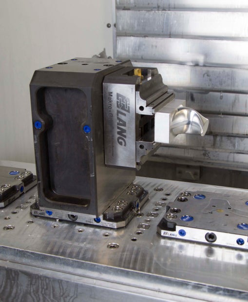
Step 8: Using the Tombstone
The Lang tombstone system is the simplest, most efficient way to machine a small part from multiple angles on a 3-axis machine. The tombstone is installed inside the Lang receiver plate and holds the Lang vise at a 90 degree angle. The part can be machined from the top and two sides without ever being removed from the vise.
You can access tombstone template files here:
P9Workholding/Haas Milll VF2/Tombstone
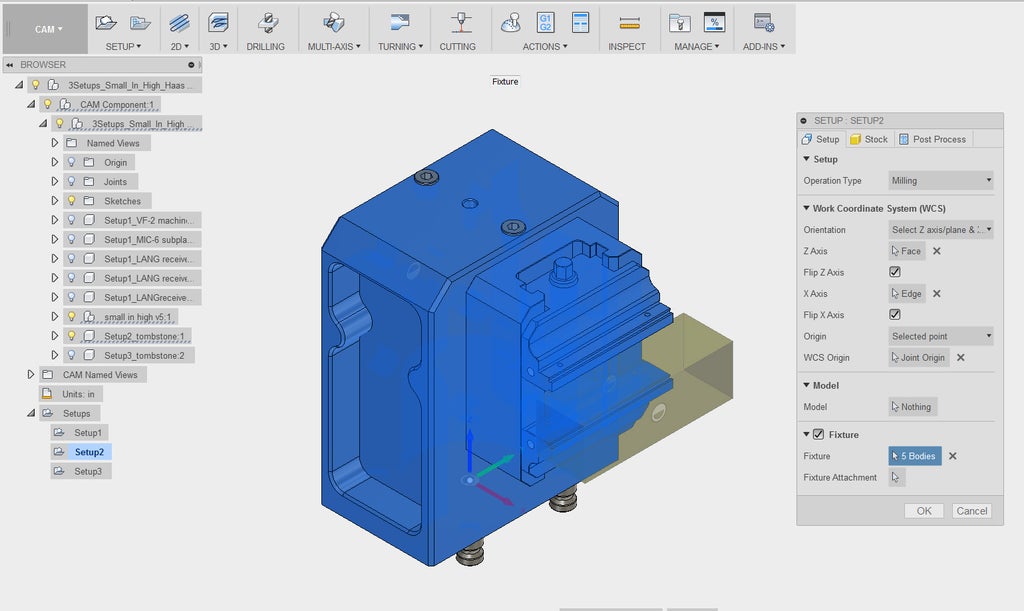
Note that in the '3 Setups' template file, there is a single vise with stock that you will join to your part when you bring it in as a component. This means you will only bring your part in once, even if you're using it for multiple setups. All the workholding solid models, such as the tombstones and machine bed, are built around this vise and are only relevant for specific setups. The easiest way to use each workholding component is to toggle its visibility with the lightbulb icon in the browser tree on the left. Each workholding object has a setup in its name, for instance: "Setup3_tombstone".
Setup 1 in this template file does not actually use the tombstone yet, and is meant for operations that rough the majority of the part from above. Note that the visibility of the workholding solid models in Setup 2 and Setup 3 has been turned off. The Work Coordinate System has already been positioned for you:

The fixture in Setup 1 has also already been selected for you:
Setup 2 uses the tombstone with the vise installed on its right side. This is because the coolant in the Haas Mill comes from spigots on the back right corner of the spindle. Though the tombstone could have a vise on its left side, the coolant would be blocked by the tombstone and tools would wear away much more quickly.
Note that the visibility of the machine bed and receiver plates from Setup 1 have now been turned off, and Setup2_tombstone has been turned on. Again, the Work Coordinate System has been set for you:

The fixture in Setup 2 has also been selected for you:
Setup 3 also uses the tombstone with the vise on the right side, but now the vise has been turned 90 degrees. The visibility of Setup3_tombstone is now turned on, Setup 1 and Setup 2 workholding models are turned off, the Work Coordinate System is placed in the correct location, and the correct fixture is selected:
Now that you understand the software templates, follow these steps to set up a tombstone operation in the Haas Mill:
1) For Setup 1, install the vise in the receiver plate in the usual way. Center and tighten the stock and execute the program for Setup 1.
2) Remove the vise and install the tombstone in the middle receiver plate.
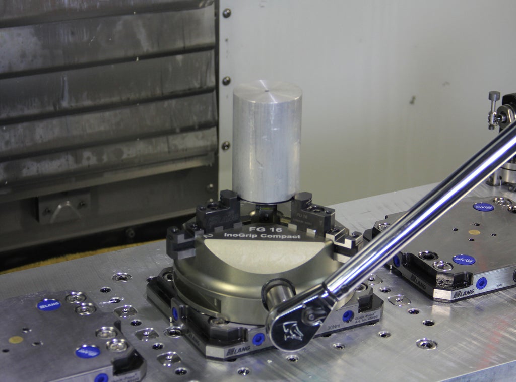
Use an 8 mm allen driver on the blue handled torque wrench set to 30 N m. Review Lesson 2 for a reminder on how to set torque levels.
Tighten until the wrench disengages with a clicking sound.

3) Install the vise with the part on the right side of the tombstone, and execute the program for Setup 2.
Again, use an 8 mm allen driver on the blue handled torque wrench set to 30 N m and tighten until the wrench disengages with a clicking sound.
After finishing Setup 2, remove the vise, turn it 90 degrees, re-install it on the right side of the tombstone, and execute Setup 3.
The tombstone system will make parts with multiple setups simpler to set up and execute with perfect registration. If you need a tombstone template that is not yet available, contact the CNC team.
Step 9: Installing the Kurt Vise
If you are probing your stock using the method you learned in the CNC Pathway and the Haas Mill machine operation course, you may choose to use the Kurt vises.
Note that the Kurt vises are not available in the template files, so your simulation detection will not be trustworthy.
Like every program, you must verify minimum part stickout to ensure you don't machine into the jaws or parallels.
In the Setup dialogue, under the Post Process tab, you will leave WCS Offset 0 to activate G54.
You could alternatively choose to build your own template file with the Kurt vise.
Follow these steps to install the Kurt vise:
1) Clean the receiver plate and aluminum Kurt adapter with a dry cloth to remove chips and debris.
If necessary, remove blue hole plugs by cupping your hand and using compressed air.
For holes you will not need, replace blue hole plugs to prevent chips from getting inside the receiver.
2) Install adapter by placing clamping studs in the bottom of the adapter inside the holes in the receiver plate.

3) Secure the adapter to the receiver plate.
Use an 8 mm allen driver on the blue handled torque wrench set to 30 N m. Review Lesson 2 for a reminder on how to set torque levels.
Tighten until the wrench disengages with a clicking sound.
4) Install Kurt vise on adapter.
Use two 1/2" 13 bolts and a 3/4" socket wrench.
5) Insert parallels and stock.
Check minimum part stickout with calipers to confirm that you will not machine the vise jaws.
Use a mallet to seat stock and parallels.
Tighten with Kurt vise handle.
Step 10: Verifying WCS G154 P1
While following the Haas Mill Quick Start Guide, remember that you will not be setting the WCS (G54) with the Renishaw probe. Instead, you will verify that the controller has the correct G154 P1 coordinates.
Replace Finding Z and Finding X and Y on pages 16-17 of the Haas Mill Quick Start Guide with the following steps:
1) Press MDI.
2) Press OFFSET until the Work Zero Offset table is highlighted white.
3) Use the arrow keys to highlight G154 P1.
Compare the numbers in the controller to the numbers stored on the sticker outside the machine. If they are different, consult Shop Staff.

Step 11: Additional Haas Mill Resources
Congratulations on completing the Haas Mill portion of the Workholding at Pier 9 course!
Here are some additional Haas Mill resources. Note that we will provide links once they are available.
The Haas Mill QuickStart Guide
A step-by-step guide for safe machine operation.

Beginner and Advanced CAM Programming Instructable
A step-by-step guide for 2.5D CAM Programming, covering Facing, Contour, Pocket, and Adaptive Roughing Operations, as well as how to prepare for flip machining.


