

Introduction: Lathe Basics


The workpiece rotates as the cutter is moved into its path.
The lathe is different from other shop tools, because it rotates the workpiece rather than the cutting tool. As the workpiece is rotating, the tool is moved in one of two axes.
The lathe is used to cut cylinders, tapers and threads on the inside or outside of the workpiece.
The headstock holds the parts that control the speed of the lathe, as well as the threading controls. It also holds the chuck and collet, which are used for workholding.
Note: Only #5 and #8 may be moved while the lathe is in motion.
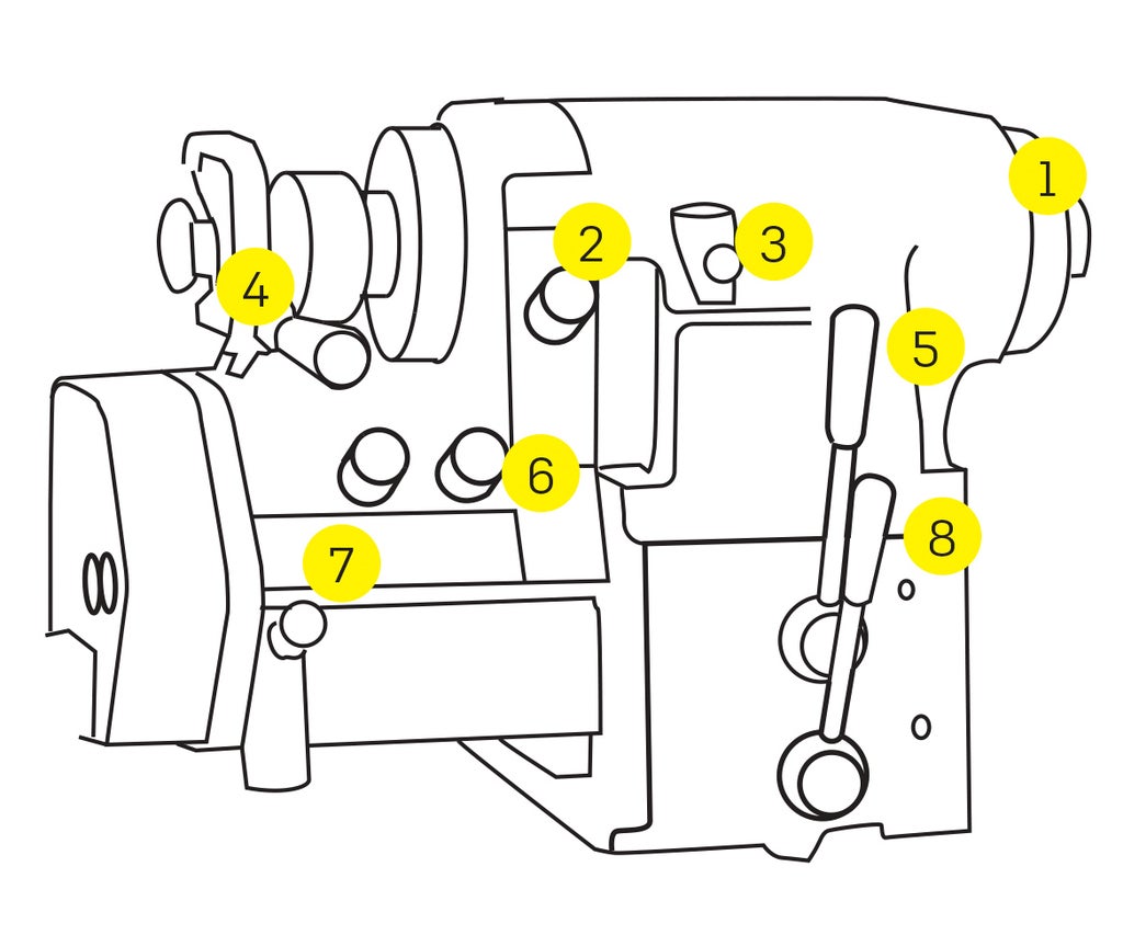
- Spindle nose
- Chucks and collets attach to the spindle nose.
- Feed/thread selector
- Selects either feeding or threading.
- Spindle lock
- Ensure that the spindle is unlocked before operating.
- Collet closer
- Threading feed direction lever
- SAE/metric threading selector
- Thread pitch controls
- Spindle speed range (hi/low) and brake lever
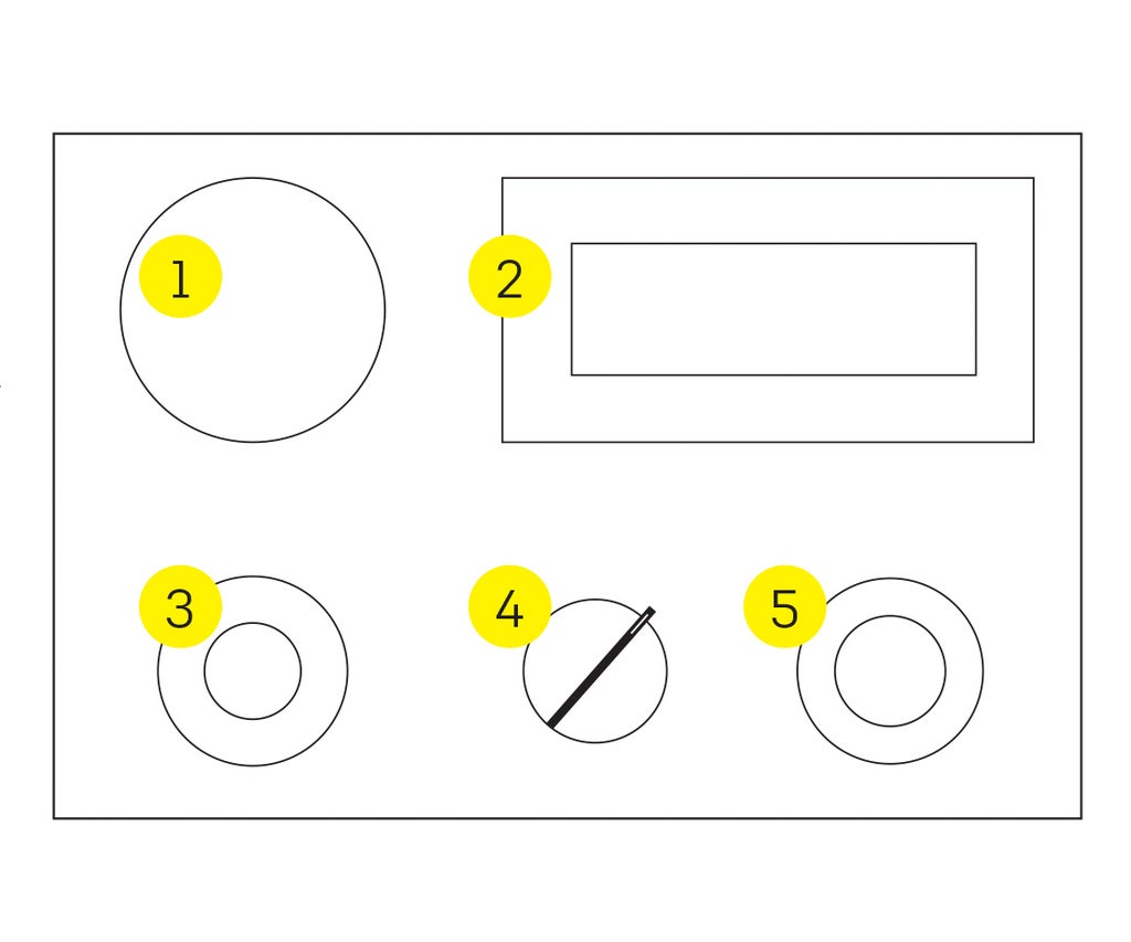
The control panel sets the spindle speed and rotation
direction. The panel is located just under the tailstock.
- E-Stop
- Speed (RPM) display
- Speed (RPM) control
- Spindle direction
- Start button

Below the headstock are a light and switch.
The Power Lamp lights up green when the power
switch is on.
The Coolant switch has three positions
- Leave the coolant switch off.
- Use a brush or dropper for coolant.
Step 1: The Carriage
The bedway (also called the ways) are the rails that the carriage rides on. They must always be protected from damage.
- Never use any kind of tool (hammer, file, scraper, etc) on the ways.
- Do not use sandpaper on the lathe, because the grit will damage the ways.
The carriage rides on the ways and holds many of the frequently used controls.
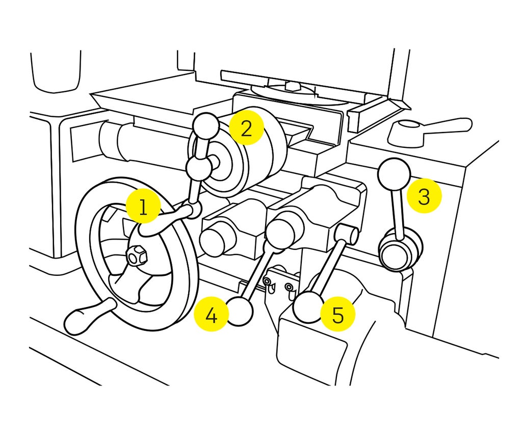
- Z axis handwheel
- Moves the carriage along the long axis (Z).
- Cross slide handwheel
- Moves the cross slide on the short axis (X).
- Threading lever
- See Shop Staff for cutting threads.
- Power feed (carriage)
- Engage the lever to move the carriage at a steady rate for a precise cut.
- Power feed (cross slide)
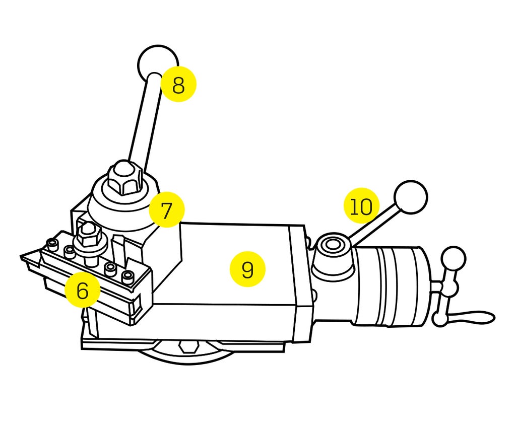
- Cutting tool (installed in a tool holder)
- Tool post
- Holds the tool holder and cutting tool.
- Can be rotated independently of the compound.
- Tool holder lock handle
- Locks the tool holder into place.
- Compound slide
- Can be rotated in order to change the angle of the tool or to cut short tapers.
- Quick lever
- Move the lever forward before starting a cut.
- When reaching the end of a cut, pull the lever back to move the cutting tool away from the workpiece.
- This allows you to clear the workpiece without adjusting the cross slide or compound slide.
Step 2: The Tailstock
THE TAILSTOCK HOLDS DRILL BITS AND SUPPORTS LONG WORKPIECES.
The tailstock is commonly used to hold a drill chuck or a live center.
- The drill chuck is used to hold drill bits for drilling into the end of the workpiece.
- The live center is used for supporting long workpieces.
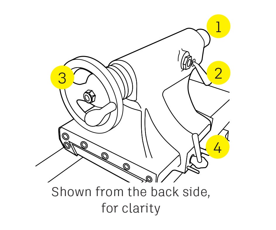
- Quill
- Located inside the tailstock, and can be extended or retracted.
- Inside the quill is a tapered hole that holds the accessories.
- Quill lock
- Quill handwheel
- Extends and retracts the quill along the long axis (Z).
- Tailstock lock
- Locks the tailstock to keep it from sliding along the ways.
USING THE TAILSTOCK
Be aware that sliding the tailstock too far down the ways can cause the tailstock to fall off the lathe.
+ Do not slide the tailstock all the way to the end of the lathe.
Installing a tapered accessory
The two tapers must be exactly the same (on this lathe, it's a size 2 Morse Taper). See Shop Staff for assistance if needed.
- Unlock the quill lock.
- Lock the tailstock.
- Adjust the quill so it is sticking out 1/2" to 1".
- Clean the inside of the taper on the quill.
- Clean the outside of the taper on the accessory.
- Slide the tapered accessory into the taper of the quill.
- Ensure that the tang on the taper is vertical.
- If the tang does not line up with the vertical slot inside the taper, it will not go in.
- Gently slide (but with some force) the accessory into the taper to seat it.
- It is OK to give the drill chuck a soft hit with a deadblow hammer to help seat it.
- Retract the jaws of the drill chuck before striking it.
- Never use a metal hammer.
Removing the accessory
- Loosen the quill lock.
- Fully retract the quill, and remove the accessory by hand.


