

Introduction: Printing Style, Orientation and Slicing


You have several options for printing the model.
Step 1: Select the Infill and Support Style

The model will be printed with a solid exterior, but there are options for how the rest of the model is created.
- In the Modeler Setup dialog, select options for Interior (infill), Surface & Support.
Step 2: Part Interior Options

Solid - normal
- This will create a completely solid model.
- It is the strongest option but will be heavier, more expensive and take longer to print.
Sparse
- Alternating layers of diagonal lines will be printed.
- This option creates a mesh interior that is lighter, less expensive and faster to print.
Sparse - double dense
- Every layer gets a diagonal line in both directions.
- This option creates a mesh interior that is stronger than sparse, but still light, inexpensive and fast to print.
Visible surface style
- In most cases, you should select Enhanced. It creates a slightly nicer print and will take slightly longer to print.
Step 3: Support Style Options
SMART
- SMART uses the least amount of support material and prints faster than the other options.
Sparse
- This option is stronger than SMART, but uses more material.
Basic
- Basic uses even more material.
Surround
- Designed for tall thin parts, it completely surrounds the model.
Break-away
- Designed to be easy to remove, but is not as supportive as the other options.
Step 4: Part Orientation
Part Orientation will impact several factors
Choose an Orientation
Changing the orientation of the part (which face sits on the build platform) is influenced by five factors.
Height and size
- Z is the slowest axis to print.
- A tall print will take longer to print than a short print of the same volume.
Support material
- Switching build material and support material takes at least 30 seconds per layer. A layer without support will print faster than the same size layer with support.
- Some support material may be hard to remove, such as inside of pockets.
Part strength
- Since the model is printed layer by layer, the joint between layers is the weakest spot.
Surface quality
- Parts with a gentle curve on the top surface will have a stair-step effect.
Airflow inside the build chamber
- Consistent airflow and temperature helps model quality. Air flows in from the sides of the oven.
- Placing tall models in the center, rather than the edges, helps to keep airflow regular.
- Placement in the build chamber is handled at a later step.
Orient the Part
There are two fast options for part orientation.
Automatic Orientation
- Select this option from the STL menu.

Manual Orientation
- Click the Orient Part button in the toolbar.
- Click the desired orientation from the menu.
- Click that surface of the model.
- For example, clicking Right, then selecting a surface of the model will orient the model so that face is to the right.
More options
- Rotate... will allow you to rotate the model around the X, Y or Z axis.
- Units and scale... will allow you to change the units (inches or mm) or to scale the model.
Step 5: Slice the Model
Create toolpaths and inspect the layers
SLICE THE MODEL
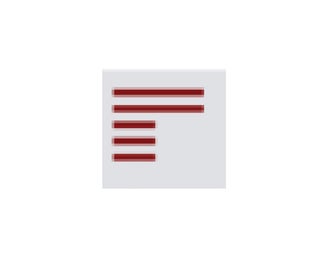
Click the Slice icon.
Models generally have hundreds of slices.
The STL file will be hidden. The red lines represent the slices.

- Once the model is sliced, it cannot be modified without deleting the slices.
- Select Slice > Setup.
- Click the Delete Slices icon.
CREATE SUPPORTS
Models with overhanging or cantilevered elements will distort if they are not supported. The software creates supports for any surface at less than a 45 degree angle, but this can be changed in the software. See Shop Staff for assistance if working from Pier 9.
- Click the Create Supports icon.

CREATE TOOLPATHS
Click the Create Toolpaths icon.
- A toolpath is a path that the extruder head will follow to lay down the filament.
Step 6: Inspection
INSPECT THE LAYERS
Inspecting individual layers can help identify problems with the model.

Show the toolpaths
- Choose Shade toolpaths from the Toolpaths menu.
- Click the Display Top icon.


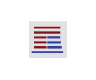
INSPECT TOOLPATHS & SUPPORTS
You may want to review the toolpaths and supports. Deleting unneeded support can speed your print times.
- Slice lines will be red.
- Model material will be green.
- Support material will be blue.
To estimate the print time, select Toolpaths > Estimate Time.
This will allow to see the time savings when editing the model settings.

- To delete unnecessary support material, select Toolbox from the View menu.
- Click Delete in the Toolbox.
- Select Support Material Curves from the Selection Tools menu.
- Curves are what the software calls the lines.
- This option will only select support material, so you don't accidentally delete model material.
- Click OK to delete the support path.
- Click a line (or drag for multiple).


