

Introduction: 3 Axis Arduino Based CNC Controller


I've been playing with different CNC designs and Stepper controllers for many years now. I started building CNC machines long ago. My first inspiration came from Bruce Shapiro’s eggbot. I tried a few variations of it and even the board from evil mad scientist. Recently a project named GRBL came along that caught my eye. It used an Arduino to do the G-Code Interpretation. It still outputs step and direction pulses so all my existing designs worked fine with it.
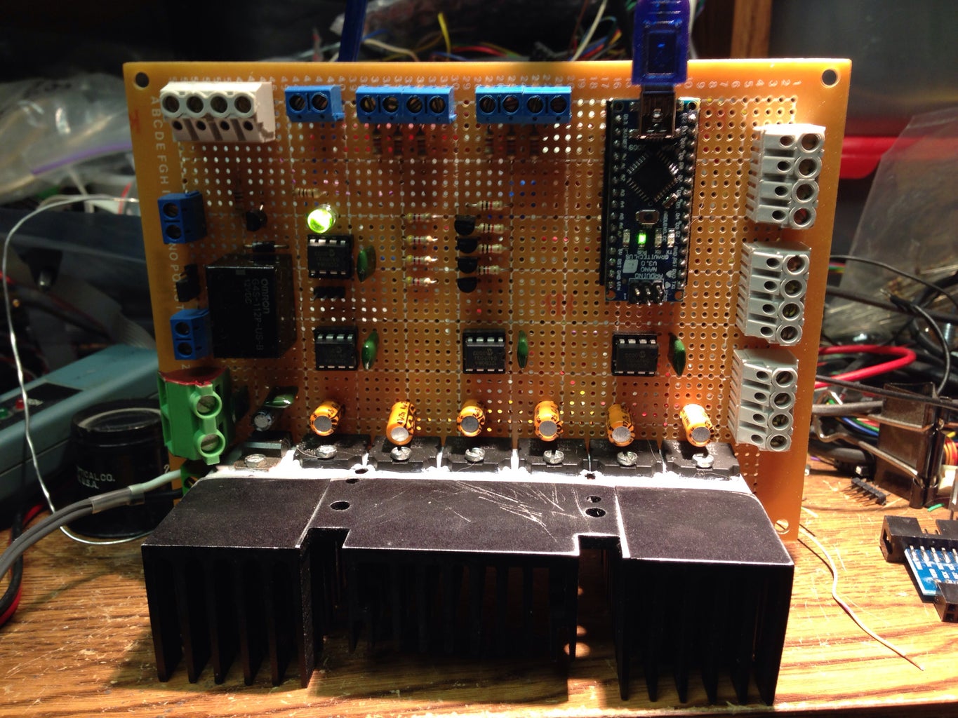
The latest generation controllers I have built all use the same simple and cheap IC's. A pic 12c508 as the basic stepper driver logic and some H-Bridge chips that were originally meant for mundane things like tray loading motors on dvd players. I got a couple of hundred of these on ebay. The pic micros were from a guy that used to do mod chips with them but sold out his stock of unused chips really cheap.
I've used the cheapest parts I could find and still got great results with modest fine tuning. I used a dial indicator to see how bad my table was and it only varied .008 inches in depth from end to end. If I had used a surface planed board or aluminum plate that would have been better. I could always just mill a huge squared spiral pattern into the table to make it perfect
Step 1: Single Board or Multiple Board Modules


I've tried both ways and each has its advantages. I always keep the 110V SSR board separate. When using the single board approach I like to use an Arduino nano clone. when using multiple boards I use and arduino prototype sheild wired with a bunch of headers for the individual boards.
Step 2: Control Buttons


I found these nice buttons in a surplus shop so I bought a bunch. A scrap of aluminum angle iron, a drill press, and a bandsaw made a couple of quick panel.s You can easily do this with a hacksaw and hand drill.
Step 3: 110V Solid State Relays
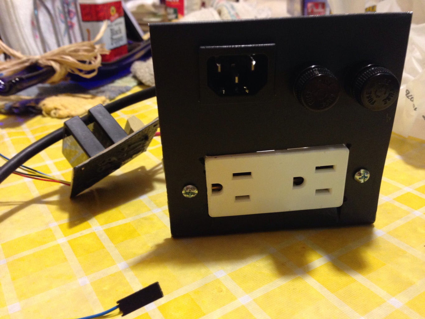

the great thing about certain SSR modules is they operate on 3-36V input signal. that even works well with a raspberry pi. I used 2 relays. one for spindle control and the other for coolant. I never really use liquid coolant. just a shop vac plugged into that port. Makes a great way to tell when the part is done since it gets real quiet in the workroom. I actually put a webcam on it so I could watch it from upstairs and not have to listen to the noise
Step 4: Picking Motors
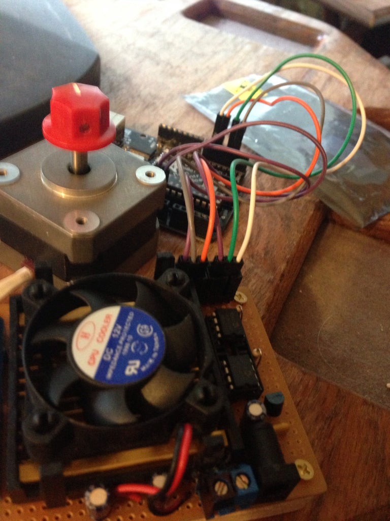
Picking motors is the hard part. They have to be beefy and easily available. for me that meany craigslist and an ad begging for old plotters and massive printers from the dot matrix days. Luckily I got a recycler to give me a pickup truck load of them
I use a simple driver that has no enable input but is really cheap to build and can handle 90W/per motor max (30V and 1.5A/phase). it does have overcurrent , overvoltage, overtemp protection though. I am writing an i'ble just on that controller. I like to use recycled power bricks in the 16-19V range.
that works well since I had a bunch of unipolar 12V steppers. I don't connect the common leads so I use an H-Bride bi-polar driver. this means the 12 coils on each phase are connected in series for a 24V coil. Running them at 16V keeps them cooler.
Step 5: Software

The GRBL firmware was simple since I used the sketch version so I could load it using the arduino IDE. I foung the GRBL Controller just as easy to use and there are windows and Mac versions available...
Step 6: X-Y Test
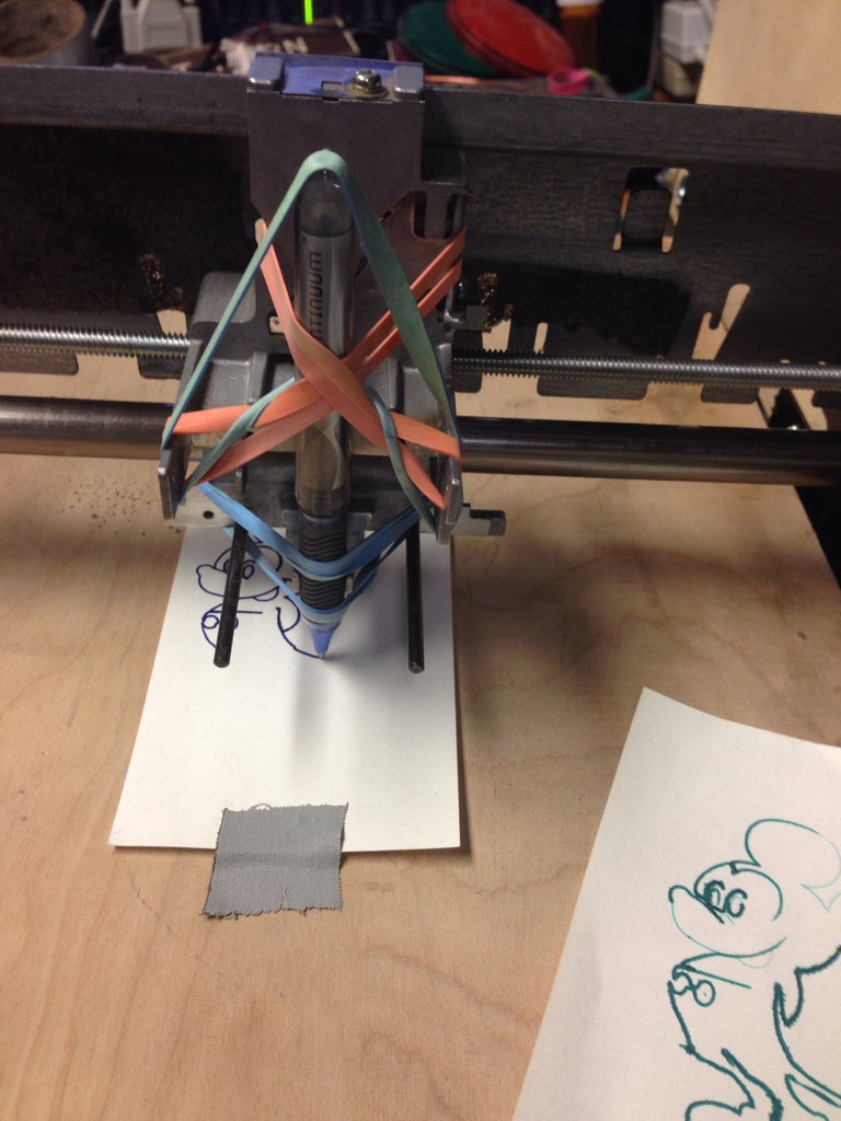


I wanted to see just how well the x-y table worked before continuing so I loaded up a simple g-code mickey mouse file and put a pen in the machine with a bunch of rubber bands. This also made it easy to test out acceleration settings since I could hold successive prints up to the light.
I worked by trial and error increasing the feed rate and acceleration until it lost steps then backed off a bit. In the real world I used a slower rate anyway so as not to break off the carbide bits.
I worked by trial and error increasing the feed rate and acceleration until it lost steps then backed off a bit. In the real world I used a slower rate anyway so as not to break off the carbide bits.
Step 7: Z Axis

The Z axis had to be strong enough to hold a dremel but not too heavy to stress the motors. I used some okidata printer rails and 1x4's. in another version I used the rails from an old laserdisk player bolted to a 1x4.
for all the axis' i used 1/4-20 threaded rod. To minimize backlash I used blocks of delrin to make the nuts
for all the axis' i used 1/4-20 threaded rod. To minimize backlash I used blocks of delrin to make the nuts
Step 8: Trivets


I finished it on Christmas eve and decided to make some trivets and ornaments for stocking stuffers.
I used scraps of flooring, shelf boards and whatever else I could find laying around the shop.
to give the engravings more contrast I used some spray paint. I just gave the board a liberal coating and wiped it down with a rag sprayed with WD40
I then used mineral oil to give the wood a little protection
Step 9: Circuit Board Routing


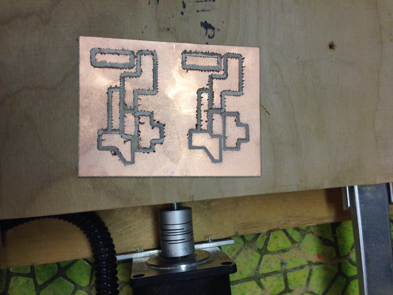


A little while later my friend John was visiting and asked if it could drill a circuit board. I said sure, it could even route them too
So I decided to give it a try. I found a simple QRP transmitter design which I could use for an arduino project and tried to make a couple.
I built a 20M and a 40M board. They worked so well I’m going to route 2 more for 80M and 160M
