

Introduction: 9*9 LED Matrix With Arduino

Ever wanted to have a bigger display?
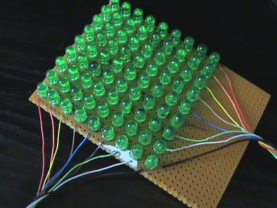
This display is based on an 9*9 green LED Matrix. The display is driven just with one Arduino board (Duemilanove in my case).
Why do we use a matrix and we don't light's up the leds individually?
Basic :
A led have 2 pin's: anode & cathode.
So even we put the led's with the common cathode, we will still have 81+1 pin's, the arduino board isn't enought for this.
In a matrix we can put the columns to the cathode and the rows to the anode of the Led's, so here we will have just 9+9 pin's, better then the other but a little tricky on the programming stuff.
Step 1: Basics


What do you need :
- 81 green LED's (or other color)
- an test PCB
- and an arduino board
next we need the schematics :
Matrix hardware
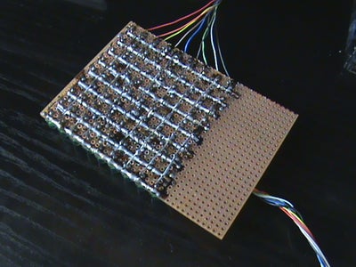
I have build the matrix like next :
- the columns have the cathode's of the LED's
- the rows have the anode of the LED's
Arduino Pin's :
Now we will have to connect the matrix to the arduino board :
the rows :
- the row 1 to digital pin 0
- the row 2 to digital pin 1
- the row 3 to digital pin 2
- the row 4 to digital pin 3
- the row 5 to digital pin 4
- the row 6 to digital pin 5
- the row 7 to digital pin 6
- the row 8 to digital pin 7
- the row 9 to digital pin 8
the columns :
- the column 1 to digital pin 9
- the column 2 to digital pin 10
- the column 3 to digital pin 11
- the column 4 to digital pin 12
- the column 5 to analog input pin 0 (there is no problem we can use it like a digital one, i'll show you later)
- the column 6 to analog input 1
- the column 7 to analog input 2
- the column 8 to analog input 3
- the column 9 to analog input 4
- 81 green LED's (or other color)
- an test PCB
- and an arduino board
next we need the schematics :
Matrix hardware
I have build the matrix like next :
- the columns have the cathode's of the LED's
- the rows have the anode of the LED's
Arduino Pin's :
Now we will have to connect the matrix to the arduino board :
the rows :
- the row 1 to digital pin 0
- the row 2 to digital pin 1
- the row 3 to digital pin 2
- the row 4 to digital pin 3
- the row 5 to digital pin 4
- the row 6 to digital pin 5
- the row 7 to digital pin 6
- the row 8 to digital pin 7
- the row 9 to digital pin 8
the columns :
- the column 1 to digital pin 9
- the column 2 to digital pin 10
- the column 3 to digital pin 11
- the column 4 to digital pin 12
- the column 5 to analog input pin 0 (there is no problem we can use it like a digital one, i'll show you later)
- the column 6 to analog input 1
- the column 7 to analog input 2
- the column 8 to analog input 3
- the column 9 to analog input 4
Step 2: The Analog Pin's
We have connected the columns 5, 6, 7, 8 & 9 to the analog input's 0, 1, 2, 3, 4 on the Arduino board.
On the columns we have the cathode's from the led's so we need an input here, but if we will have an input the port we will be always open so the column we will be always on when we will output the rows.
To avoid this we will make the analog input pin's to be used like outputs.
To do this we use the command :
"pinMode(col[thisPin], OUTPUT);"
What's with all the stuff there, in next section.
Step 3: Programming Setup
First we need to define the pin's.
and you need to know that in digital mode the analog input pin's are defines like : 14,15,16,17,18,19.
we have row's and column's so :
const int row[9] = { 0, 1, 2, 3, 4, 5, 6, 7, 8 }; // the anodes
const int col[9] = {9, 10, 11, 12, 14, 15, 16, 17, 18}; // the cathodes
next we need to setup the matrix
void setup(){
for (int thisPin = 0; thisPin < 9; thisPin++){
//we initialize the pins as output's
pinMode(col[thisPin], OUTPUT);
pinMode(row[thisPin], OUTPUT);
// now we have to make the columns high so that all the LED's will be off
digitalWrite(col[thisPin], HIGH);
}
}
void loop(){
}
this is the setup stuff
next we play
Step 4: Programming : Light Up the Diagonal
In the last section we made the setup.
Now let's light up the diagonal
First you need to know that if you what to light up just the diagonal you need to turn one the first row ... turn it off then turn on the second row .... turn it of and so on, you must do this fast so the eye don't observe.
This principle is used on the tv's
now in loop()
we have to do something like this :
for ( intPin = 0; Pin < 9; Pin++){
digitalWrite( row[Pin], HIGH); // the anode is high
digitalWrite( col[Pin], LOW); // the cathode is low
// this turn the led on now we have to let the led on for some time .... 1 microsecond is enough
delayMicroseconds(1);
//now we have tu turn it off so we will inverse the polarity
digitalWrite( row[Pin], LOW); // the anode is low
digitalWrite( col[Pin], HIGH); // the cathode is high
//we have turn the led off, next delay it 1 microsecond and go to the next row
delayMicroseconds(1);
}
We have finish, now we have the diagonal of the matrix on
Let's do something more complex :
Step 5: Programming : Complex Stuff
If we want to build something more complex and use the last method is a little hard.
But we can do something like this :
int the loop() function :
// first we have to build the matrix in arduino with the shape that we want
int matrix[9][9] = {
{ 0, 0, 0, 0, 0, 0, 0, 0, 0 },
{ 0, 0, 0, 0, 0, 0, 0, 0, 0 },
{ 0, 0, 1, 1, 1, 1, 1, 0, 0 },
{ 0, 0, 1, 0, 0, 0, 1, 0, 0 },
{ 0, 0, 1, 0, 0, 0, 1, 0, 0 },
{ 0, 0, 1, 0, 0, 0, 1, 0, 0 },
{ 0, 0, 1, 1, 1, 1, 1, 0, 0 },
{ 0, 0, 1, 0, 0, 0, 1, 0, 0 },
{ 0, 0, 1, 0, 0, 0, 1, 0, 0 }
}
// i have draw an A there, you can draw anithing
// next we have to light up the led's like in the matrix
// first we will make a while that repeats to the infinite, to have the letter on all the time
while(1){
for ( int L = 0; L < 0; L++){ // the "for" for lines
for ( int C = 0; C < 9; C++){ // the "for" for columns
//we verify in the matrix if we have 1 - the led is on
if ( matrix[L][C] == 1){
// if we have 1 in the matrix we light up the corresponding led on the matrix
digitalWrite ( row[L], HIGH);
digitalWrite ( col[C], LOW);
delayMicroseconds(100);
}
// here we turn the led's off
digitalWrite ( row[L], LOW);
digitalWrite ( col[C], HIGH);
delayMicroseconds(100);
}
}
}
so that was it
next some movies and a file with scrolling text.
Step 6: Videos
Movie's

