

Introduction: Arduino : How to Control Servo Motor With Potentiometer


This instructable is the written version of my "Arduino : How To Control Servo Motor with Potentiometer" YouTube video that I've uploaded recently. I strongly recommend you to check it out.
Step 1: Tutorial
Control the position of a RC (hobby) servo motor with your Arduino and a potentiometer.
*** I recommend! You not connect directly the servo motor to arduino. I suggest you use external power to the servo.
SG90 Mini RC servo motors can be used. This can damage the Arduino MG996 instant high torque.
MG996 Stall Torque: 9.4kg / cm (4.8V) - 11 kg / cm (6.0V) and Operating voltage: 4.8 ~ 6.6v.
I wanted to tell in this tutorial; connections, code generation and motor control. So I did not give more details about the engine.
Step 2: Hardware Required

Hardware Required
- Arduino or Genuino Board
- Servo Motor
- 10k ohm potentiometer
- hook-up wires
- mini breadboard
Step 3: Circuit
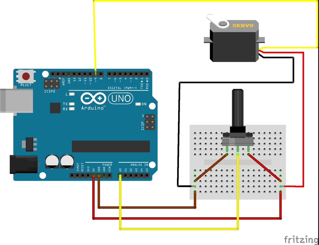


Servo motors have three wires: power, ground, and signal. The power wire is typically red, and should be connected to the 5V pin on the Arduino or Genuino board. The ground wire is typically black or brown and should be connected to a ground pin on the board. The signal pin is typically yellow or orange and should be connected to pin 9 on the board.
The potentiometer should be wired so that its two outer pins are connected to power (+5V) and ground, and its middle pin is connected to analog input 0 on the board.
Step 4: Code

This example makes use of the Arduino servo library.
Step 5: If I Was Helpful

First of all, I would like to thank you for reading this guide ! I hope it helps you.
If you want to support me, you can subscribe my channel and watch my videos.
