

Introduction: Arduino LED Backlight Clock With Pulsing Minute Hand


Hi, Everyone,
I had the idea for this when I was playing around with some LED backlights. They are very cool and I thought they would be good as the hands for a clock. The idea was that the minute hand could gently pulse around the clock as a bunch of flashing LEDs. Since I knew how to make LEDs pulse with PWM, all I had to do was figure out how to control twelve of them with the limited PWM pins on the Arduino. So I went online, and with a bit of research, and found the TLC5940. So I set about building the clock.
I used an analog voltmeter (5V) in the middle to indicate the number of minutes past the fifth minute intervals (See Picture) and I replaced the backing to make it into minutes. (This has been done before in other projects). I used Inkscape to redraw the backing and printed on a standard printer.
I also had the idea that I would use an auto dimming Light Dependent Resistor circuit to make sure that the Clock never overpowers a room when it is dark. You can see that in the image just below the panel meter.
It turned out pretty well as you can see from the pictures and you can see the action on the video attached. (watch it to the end to see the clock change)
I hope you enjoy this Instructable.
Step 1: What You Will Need.


So here is what you will need;
- An analog 5V dc Panel Meter
- Arduino UNO or other Arduino.
- Aduino Proto Board.
- A DS1307 real time clock module.
- A TLC5940 Breakout Board.
- 12 X LED Backlights
For the other parts in this project, I am fortunate enough to have access to a 3D printer and a Laser cutter. I am sure you could manufacture some of the parts by hand but I will include all the designs and drawings, so that, if you can find a nearby Makerspace, you might be able to have them produced.
Most of this stuff i had lying around, but I suppose the LEDs are the expensive part at £1.49 each. Altogether the cost is about £80.
Step 2: The Clock Face


I decided to create the clock face from three layers of laser cut 3mm MDF, which I would be able the bolt together. The donut shaped plate (bottom Right) is placed beneath the other LED Positioning plate (Bottom Left). The individual LEDs are then placed in their positions and the face plate (Top Middle) is placed on top. I had cut four small holes around the rim of the clock face to allow me to screw them together to hold the LEDs in Place.
Notes
- To test the LEDs or the right way up. I used a CR2032 coin cell to
- I did use a little bit of tape on the back of each LED whilst I was building this.
- I had pre-bent all the legs of the LEDs to keep them out of the way of each other.
- I re-drilled the holes at the edge later and used bolts to hold them together. It turned out to be more convenient.
Attachments

Step 3: Working Out the Circiut


It took me a while to work out the wiring for the clock. It was mainly done from examples and tutorials for the two devices I was using. Namely the RTC module and the TLC5940. I used the Buildr tutorial for the 5940 and the RTC provided by Sparkfun to figure out the wiring. I have uploaded the Fritzing file and a PDF Schematic. Inscrutables provided the wiring and tutorial for the LDR.

Step 4: Wiring the Arduino Proto Board


I'll start this with a disclaimer. I am not sure if I am using the Proto board correctly, but this is how I did it.
- The first thing was to solder in all the header pins for the proto and breakout boards.
- My prototype told me that a lot of the breakout and peripherals used 5V and Ground, so I soldered in a couple of wires to the 5V and Ground on the Proto board.
- Next I decided to position the TLC5940 near to the pins it used.
I proceeded to wire the TLC5940 using my schematic for reference.
I soldered the RTC module at the edge of the board. because I needed it to have an accessible battery, If I soldered it in the middle of the board I couldn't see the labels on the pins.
I then wired in the RTC Using the Schematic.
I then wired the circuit for the LDR.
Then the leads between pin 6 and ground for the Panel Voltmeter.
- Finally I soldered the thirteen LED wires (In hindsight, I should have soldered in the 13 LED leads before Step 3. It was very awkward to do last thing)
Step 5: The Code
As I said earlier the main code was a cobble together of the examples I found online. (RTC, TLC5940, LDR).
The main Difficulty in the code was that I wanted to fade the LED representing the minute hand in and out (see Video). I spent a lot of time trying different "for loops" in my code, but it always ended up getting messed up with the timing of the Arduino. In the end I opted to use the main loop of the Arduino and just put counters within it. I have attached a full copy of the code along with some comments in it.
If anyone can find a better way of doing this then feel free to comment.
Points to watch out for:
- When you flash it to Arduino the line that sets the time below, needs uncommenting.
rtc.adjust(DateTime(__DATE__, __TIME__))
- Then you need to flash it again with this line commented out. This allows the RTC module to use the battery to remember the time in the event of power loss.
- Every time you use a "Tlc.set()" you need to use a "Tlc.update"
Other than that I hope the comments in the code are enough
Attachments
Step 6: The Outer Ring
I have attached the design for the 3D Printer to produce the outer ring for the clock. I drew it in solid works and printed it on a Replicator Z18. It attaches to the clock via the screws on the face of the clock.
Attachments

Step 7: Building the Clock

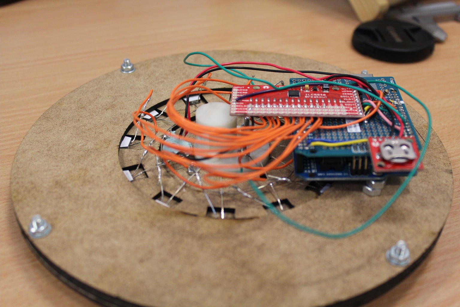
I attached the Arduino to the back of the clock using a couple of self tapping screwand some M5 nuts as spacers. (you could use proper spacers but i didn't have any lying around the Lab.) I then wired in all of the LEDs, the Analogue voltmeter and the LDR to the flying leads i had left on the proto board. I wired the long leg of the LEDs together because they all go the the VCC pin on the TLC5940. You can just see the circular piece of wire I used to solder them together in the image.
The whole thing is not very well insulated from short circuits, But I intent to work on that in the next iteration.
Once this was done I fitted the whole thing into the outer ring and it was done.

Runner Up in the
Arduino Contest 2016


