

Introduction: Arduino Matrix Clock

So, a little introduction as to why I made this project. For school we needed to make an interactive arduino project and because I'm not the best programmer in the world so I've chosen to make an interactive matrix clock.
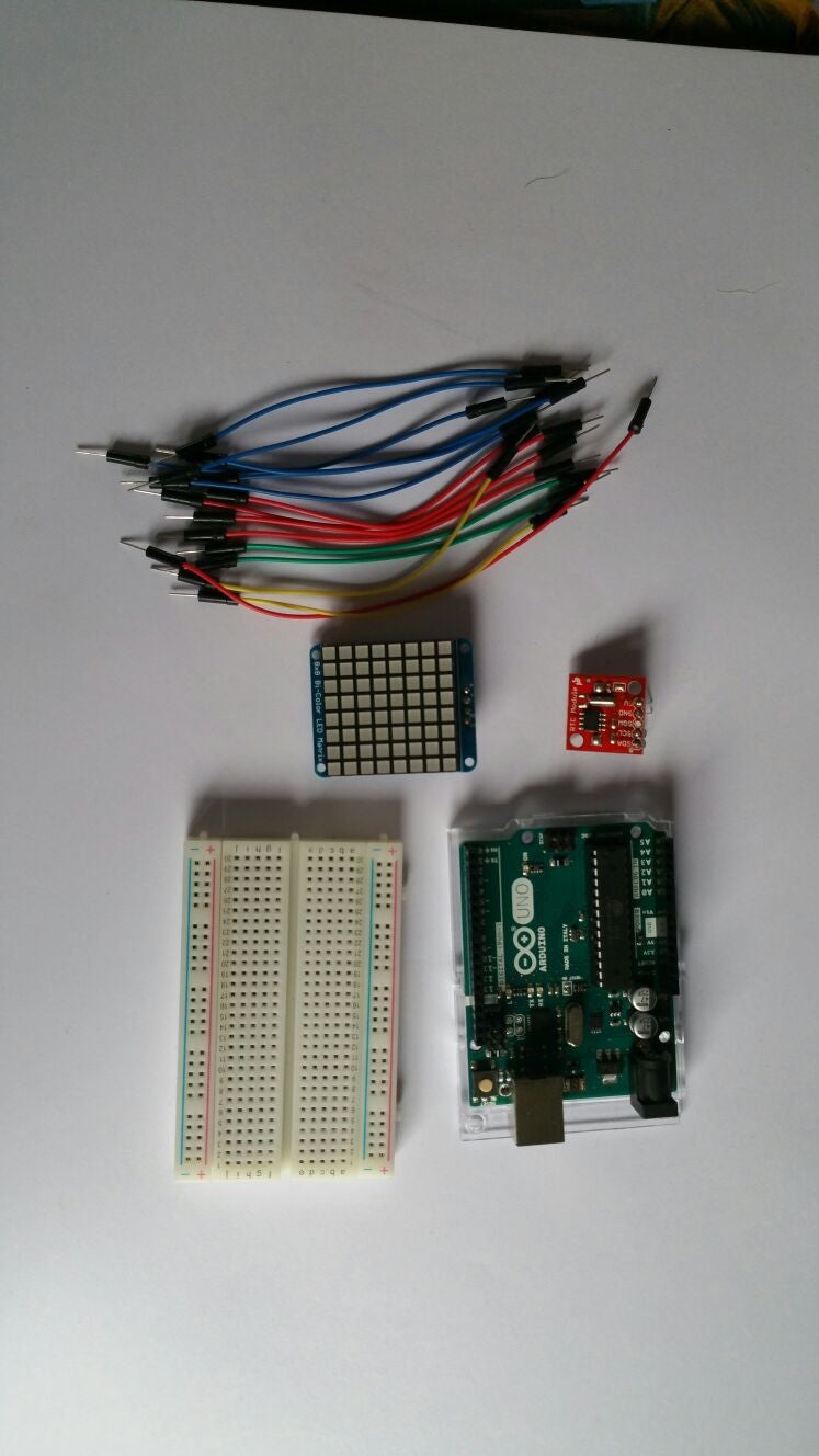
Step 1: Materials
The instructions will be for the display and RTC module. I couldn't figure out how to get the gyroscope module working, so bear that in mind.
For this project we will need:
- 1x Arduino (UNO) **
- 1x USB to micro-USB cable
- 1x Breadboard
- 1x 8x8 bi-color LED Matrix
- 1x HT16k33 LED Backpack
- 1x RTC (Real Time Clock) Module (DS1307
- 1x 4 pin connector *
- 1x 5 pin connector/ 2x 2 pin connector *
- 10+ Breadboard wires
* (This is so we can easily work with the modules on the breadboard)
** (Other Arduino's should work as well)
Step 2: Matrix Display and Backpack

Before we can start working on anything else, we need to attach the backpack of the matrix display. Just put all the pins of the display through the holes of the backplate and solder them in place. Be careful that the solder does not touch any other pins, this will cause a row of pixels to not function properly.
Once you've done all that, you'll need to solder the 4 pin connector to the backplate, this is so it's easy to test the display on the breadboard. You can also choose to directly connect the backplate with wires to the Arduino.
Step 3: The Circuit


So now we have the display ready to go, we need to get the circuits right. In the images provided above you can see the circuits I've made. Sadly circuits.io did not have the matrixdisplay nor the RTC module. Because of this, some additional information might be handy:
- On the Matrix Display there are 4 connections, on the picture of circuits.io it's the one on the left without any space between the wiring. The red wire goes to the 5V input, the blue wire goes to ground, the green wire goes from SDA to A4/SDA and the yellow wire goes from SCL to A5/SCL.
- On the RTC there are 4 connections, but we are only going to use 4 of them. The wiring on the RTC is the same as on the Matrix Display, so: Red - 5V, Blue - Ground, Green - SDA and Yellow - SCL.
Step 4: The Code + Setting Up RTC
Before you can use the code I'll provide, you'll need to set up the real time clock module. So to start, remove the battery from the holder while the Arduino is not powered or plugged into USB. Wait 3 seconds and then replace the battery. This resets the RTC chip. Now load up the following sketch (which is also found in Examples→RTClib→ds1307) and upload it to your Arduino. **(Don't forget to download the RTC library before doing this. The library can be found here: https://learn.adafruit.com/ds1307-real-time-clock-... )**
Now when you have the RTC module all set up, it's time to upload the code.
Attachments

Step 5: Further Instructions
When I get the Gyro-scope working with the clock, so you can turn it on it's side for a different display. I'll update this post.
