

Introduction: Arduino and DIP, Rotary, Toggle, Push Button Switches


Abstract
In Embedded system design Dip, Rotary, Toggle and Push button switches are used for key in the user inputs. This article, discuss about connecting / detecting those switch changes and enabling / disabling the corresponding LEDs.
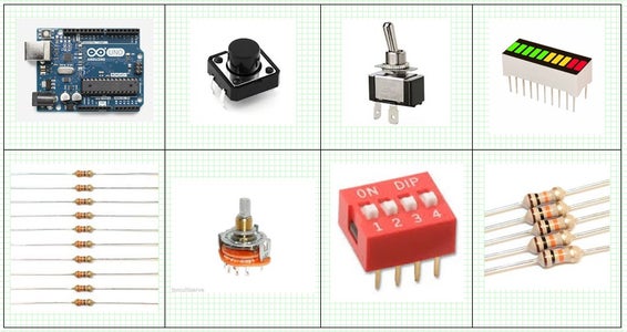
Parts and components
Arduino Uno board
330 Ohm resistor = 10 Nos
10K Ohm resistor = 10 Nos
Bargrpah display = 1 No
Single pole 4 way rotary switch = 1 No
4 way DIP switch = 1 No
Toggle switch = 1 No
Push button switch = 1 No
Step 1: Schematic

The 10 LED’s bar graph display is connected to the Arduino (2,3,4,5,6,7,8,9,10,11) digital IO pins through 330 ohm current limiting resistors.
DIP switches are manual electrical switches arranged and packed in Dual Inline Package. Can be directly solder into PCB. Commonly used to select the operating modes of an electronic device for specific situations.
A 4 way DIP switch is connected to ADC0, ADC1, ADC2 and ADC3 analog input pins of Arduino, which is configures as digital IO.
A Rotary switch operates by rotation of its spindle / shaft. Rotary switches are chosen when more than 2 positions are needed.
A four way, single pole rotary switch is connected to the ADC4, ADC5 analog input pins of Arduino, which is configures as digital IO. And another two contacts are connected to 12, 13 Digital IO pins.
A Toggle switch as projecting lever that can moved up or down. That movement will break or close the circuit / contact. Commonly used to feed the user input.
A toggle switch is connected to Pin One of Arduino digital IO.
A push button switch is a momentary or non-latching switch which causes a temporary change in the state of an electrical circuit only while the switch is physically actuated. An automatic mechanism (i.e. a spring) returns the switch to its default position immediately afterwards, restoring the initial circuit condition.
A push button switch is connected to Pin Two of Arduino digital IO.
The DIP, Rotary, Toggle and Pushbutton switches are read by the software and correspondingly activating / deactivating the LED’s at the Bargraph display.
Step 2: Software
The DIP, Rotary, Toggle and Pushbutton switches are read by the software and correspondingly activating / deactivating the LED’s at the Bargraph display.
500 milli second delay is introduced between each read / show cycle.
The project is successfully simulated by using the Proteus.
// Experiment of DIP switch, Rotary switch, SPST switch and push buttonswitch
// Name:- M.Pugazhendi // Date:- 18thJul2016 // Version:- V0.1 // e-mail:- muthuswamy.pugazhendi@gmail.com // Arduino pins used for the LEDs #define LED1 11 #define LED2 10 #define LED3 9 #define LED4 8 #define LED5 7 #define LED6 6 #define LED7 5 #define LED8 4 #define LED9 3 #define LED10 2// Arduino pins used for the switches #define S1 14 #define S2 15 #define S3 16 #define S4 17 #define S5 18 #define S6 19 #define S7 13 #define S8 12 #define S9 0 #define S10 1
// State of each switch (0 or 1) int s1_state; int s2_state; int s3_state; int s4_state; int s5_state; int s6_state; int s7_state; int s8_state; int s9_state; int s10_state;
void setup() { // pins for LEDs are outputs pinMode(LED1, OUTPUT); pinMode(LED2, OUTPUT); pinMode(LED3, OUTPUT); pinMode(LED4, OUTPUT); pinMode(LED5, OUTPUT); pinMode(LED6, OUTPUT); pinMode(LED7, OUTPUT); pinMode(LED8, OUTPUT); pinMode(LED9, OUTPUT); pinMode(LED10, OUTPUT); // pins for switches are inputs pinMode(S1, INPUT); pinMode(S2, INPUT); pinMode(S3, INPUT); pinMode(S4, INPUT); pinMode(S5, INPUT); pinMode(S6, INPUT); pinMode(S7, INPUT); pinMode(S8, INPUT); pinMode(S9, INPUT); pinMode(S10, INPUT); }
void loop() { s1_state = digitalRead(S1); digitalWrite(LED1, !(s1_state)); s2_state = digitalRead(S2); digitalWrite(LED2, !(s2_state)); s3_state = digitalRead(S3); digitalWrite(LED3, !(s3_state)); s4_state = digitalRead(S4); digitalWrite(LED4, !(s4_state)); s5_state = digitalRead(S5); digitalWrite(LED5, !(s5_state)); s6_state = digitalRead(S6); digitalWrite(LED6, !(s6_state)); s7_state = digitalRead(S7); digitalWrite(LED7, !(s7_state)); s8_state = digitalRead(S8); digitalWrite(LED8, !(s8_state)); s9_state = digitalRead(S9); digitalWrite(LED9, !(s9_state)); s10_state = digitalRead(S10); digitalWrite(LED10, !(s10_state)); //500 mS delay delay(500); }


