

Introduction: Atmel Startup 2: Microcontroller Circuits and Fuses


M. A. Parker c2015
Circuits and Fuses constructs a simple but important circuit on an experimenter’s breadboard that will be used as the basic platform for many microcontroller projects and for setting the microcontroller parameters (i.e., fuses). As the second Instructable of the series [0], we focus on ‘getting started’ with an individual Atmel Microcontroller MCU [1] as opposed to the MCU-on-a-board such as Arduino [2] and the Rhaspberry Pi [3]. The next two Startups (3 and 4) construct two versions of a ‘Blinky’, the blinking LED, to demonstrate the ‘secret’ life of the Atmel PORT, PIN and DDR registers and pull-up resistors. The fifth Instructable in the series constructs the ‘Lifeline’ from the Blinky circuit in order to correct clock fuse settings. In reality, these fuses are a type of Read Only memory that can be set by the program. As the word ‘fuse’ might imply, they can cause tremendous problems by the unwary click of a mouse button that will brick your MCU faster than you can blink your eye. It should be pointed out that the Lifeline does not correct non-clock fuses - a high voltage programmer (12V) would be required as discussed in Startup #5. The Lifeline should be considered an easy project having some post-construction worth as a means to start working with individual Atmel MCUs.
**NOTE: For those wanting the PDF of this instructable, download the attached PDF using the link below rather than the one automatically generated by the website - the automation does not maintain the association of the captions with the pictures.
As will be evident in Startup #5, the Lifeline is an easy circuit based on the Atmel ATTiny2313A microcontroller unit (MCU) that functions as a substitute clock source for a target MCU rendered inoperative by wrongly set clock parameters (i.e., clock fuses). By way of definition, the clock signal represents the ‘heart beat’ of the MCU – each clock pulse can be used by the MCU to internally gate data, initiate or read a port event, signal the Digital to Analog converter (DAC) to start reading the next voltage point and so on. The clock provides timing and synchronization for the machinations of the MCU similar to the 1-4 GHz clocks in laptop computers.
For simplicity, the Lifeline uses the internal MCU clock rather than an external crystal as will be seen in Startup #4. The clock type and speed are determined by the settings of the fuses. So we start with the fuses in this instructable. Actually, programming the fuses should probably be considered one of the first steps with any MCU project. For you see, to engage the programmer using Atmel Studio (AS), one starts the Device Programming dialog which includes the Fuse programming section.
We start by constructing a circuit on an experimenter’s breadboard that will be used for setting the fuses as well as an experimental platform for the next two articles in the Startup series. The circuit includes a 5 volt regulator for the MCU, the programmer adapter cable constructed in Startup #1, and adds an LED for Blinky and the Lifeline (but not used for the present instructable). The present Instructable will also show how to add a crystal to the MCU circuit since we will be discussing clocks and fuses.
The internet has many very good ‘getting-started’ articles and tutorials such as those listed in the references [4-9]. These are always interesting and a good source of information regarding MCU hardware and operation.

Step 1: Experimenter’s Board Circuit


Figure 2: Schematic of platform. The positive LED lead is usually the longer of the two leads – the diagrams marks the longer lead with Lg and the shorter one with St. The view shows the top side of the MCU. Figure 3: The 2313A pinout [1] for the DIP version of the ATTiny2313A.
It’s time to construct the circuit on an experimenter’s breadboard as described in Startup #1 [0.A] (see the Parts List). Beginning Startup projects should have the lowest possible parts count with the simplest possible coding. For this reason, the startup platform and Lifeline do not make use of an oscillator crystal and associated capacitors although the connections will be shown. The finished Lifeline will not use a 5V regulator although the prototype on the experimenter’s board does include it. Be aware that the supply voltage can affect the performance of the MCU as shown in the specifications for the MCU [1]. Figure 1 shows the circuit built on the experimenter’s breadboard (i.e., protoboard) while Figure 2 shows the schematic with similar parts placement as for Figure 1. These two figures show that an LED-resistor combination has been included in the breadboard circuit – the next Startup Instructables use the combination to indicate when the circuit operates. The LED and its bias resistor should be removed once the Lifeline project has been completed to save space and lower parts count in the final enclosure. Caution: Double check that the Positive battery wire (Red in Figure 1) connects to the regulator input and NOT the +5V rail running across the top of the experimenter’s board.
Construct the circuit shown in Figures 1 and 2 using an experimenter’s board [10]. A few notes are in order; however more information can be found in tutorials on the internet such as in Reference [6].
ATTiny 2313A DIP Pinout
First, Figure 3 shows how the labeling of the pins with the numbers 1 through 20 runs counter clockwise around the IC. Each pin can be used for multiple functions depending on the settings of internal registers. Generally, Atmel groups pins into ports (8pins for AVR) such as port B for pins 12 through 19 (see startup #3 for more information). Note how the programmer leads connect to MOSI (pin 17), MISO (pin 18), SCK (Pin19), and Reset (Pin 1). Refer to Startup #1 for constructing the programmer cable adapter. The programmer wires simply attach to these MCU pins as shown in Figures 1 and 2. Once the MCU has been programmed, the programmer connections can be removed. As shown in Step 2, a crystal (and two 22pf capacitors) can be attached to the pins labeled as Xtal1 and Xtal2 – the Xtal refers to Crystal and 1,2 refers to the two terminals on the crystal. The crystal can be inserted without worrying about polarity. Finally, a battery (no more than 5V) can be connected to the MCU). The negative terminal would connect to pin 10 and the positive terminal to pin 20.
Experimenter’s Breadboard
The experimenter’s breadboard provides a quick method of connecting components without soldering. Often the long horizontal electrical lines (5V rail and Grnd rail) at the top and bottom of the experimenter’s boards have a break in the underlying trace (by design). As a result, the builder must place a wire jumper across the breaks (Figure 1) to ensure continuity across the top 5V rail and the bottom Ground rail. Notice that the gaps at the jumpers are larger than the others to provide a visual cue. An ohm meter can be used to check for gaps. These long traces are generally used to distribute the +5V and logic ground across the board. We do not need these jumpers though, since we do not use the right hand side of the board.
Regulator (LM7805)
The regulator has the purpose of (i) reducing the voltage from an input of 9v to an output of 5v for the MCU and (ii) maintaining/regulating the output voltage at 5v without significant fluctuations. Actually, the input voltage can range/vary from about 7 volts up to 18v or more (depending on the regulator used) without affecting the output voltage. Without heat radiators/sinks, the current must be kept below about 100mA to prevent overheating. We use the common variety LM7805 regulator (see parts list) but be aware that these won’t function if their input voltage drops below about 7V. The Low Drop Out (LDO) regulators will function even when the input voltage drops to within a few tenths volt above the +5V output. The LDO is useful to squeeze every last bit of power from a 9V battery but they are also less likely to be in your spare parts box and they do cost a bit more. As a note, it is possible to purchase an experimenter’s board with the 5V built into it plus other goodies.
Electrolytic Capacitors (i.e., Polar Capacitors)
Capacitors store charge Q in proportion to the voltage V across them and their size C according to Q=CV. Here V is the voltage measured between the two terminals on the capacitor. In a circuit, the capacitor can often help regulate the voltage by giving up some charge. Perhaps the process might be visualized similar to a water tub with water and inside the tub there is a bucket filled with water but having a hole in the side. When the tub water drops below the hole level, the bucket will supply water through the hole to help bring the tub water level back up.
The electrolytic capacitors have + and – terminals so make sure they are properly placed in the circuit. Generally, electrolytic capacitors have capacitance over 1uF. Ceramic capacitors (and others) do not have polarity and generally have capacitance below 1uF. Make sure to correctly insert the electrolytic type since reversing it will usually destroy it and stink up the room. The negative side is often indicated with a minus sign or an arrow pointing to the negative lead. Check the manufacturer spec sheet if uncertain. The working voltage marked on the capacitor must be higher than any voltage to be applied across it. For 5V, it is ok to use least 10V or higher. I keep a good stock of 35wvdc and 50wvdc capacitors (and higher) and always use these.
Often capacitors are added to DC circuits to help filter out variations.
Ceramic Capacitors (non-polar)
The ceramic capacitors can have either terminal attached to either battery polarity. The value will be listed on the side or sometimes a code will be used instead [24]. For example, a 0.1 uF capacitor might be written as 0.1 or coded as 104 and 0.01 uF might be coded as 103. Refer to [11].
The 0.1 uF ceramic capacitor helps filter out the high frequency noise placed in the supply lines by the MCU. Generally the capacitor should be placed as close as possible to the MCU supply pins (10, 20 for the ATTiny2313A). The capacitor might be marked as 104. Refer to the capacitance code [11].
Resistors
Resistors do not have polarity. The resistor values can be determined by either using an Ohm meter (i.e., multimeter) or by reading the color code on the resistor [12]. The schematic in Figure 2 shows resistors having the value 2.2k and 10k. The ‘k’ means to multiply the value by 1000 so that 2.2k=2200 and 10k=10000. Note that sometimes ‘computerese’ uses k to mean 1024. Not here – for resistors, it means 1000. Similarly 1M means 1million. Generally, the wattage must be specified by calculating the power using Ohm’s law as P=VI = V*V/R where V is the voltage across the resistor. Generally 1/4 Watt will be OK for MCU work. Of course if lower wattage can be used, then the resistor will also be physically smaller.
LEDs
The LEDs have polarity. If they are reversed biased (i.e., terminals reverse) they won’t illuminate and can be damaged. Too high of voltage applied in forward bias can smoke them so always use a series resistor to bring the current level down to under 20mA (consult the spec sheet). The positive lead is usually indicated by the longer of the two leads. It is easy to operationally check which lead is positive by constructing the LED-Resistor combination shown in Figure 2. Once the regulator portion has been constructed, attach the battery and momentarily connect the resistor to the +5v rather than pin 12. If it doesn’t light, then reverse the LED connections. Make sure to return the wire as required in Figures 1 and 2. As an interesting side note, reversed biased LED-Resistor combinations can often be used as an optical sensor when 5v is applied across the combination and the signal is measured at the LED-Resistor connection. As for color, choose Red or Green for use with the 2.2k resistor shown in the schematic. Blue will be ok but you might want to change the resistor to 1.5k to make it brighter. It is always good to have a good supply of LEDs and resistors. Refer to the discssion in Startup #3 regarding LEDs.
Clip for 9v Battery
Solder short solid wires (24ga) to the ends of the 9v battery clip leads so as to make sure the wires securely fasten to the experimenter’s board. Generally stranded wires do not properly push into the receptacles/clips on the experimenter’s board.
Hot?
Connect a battery to the battery clip and feel both the regulator and the MCU for overheating. If either becomes finger-scorching warm, disconnect the battery fast and figure out the wiring error.
Disconnect Battery
Disconnect the battery while completing the next few sections. Do not connect the programmer to the adapter cable yet.
CAUTION
Do not connect any 5v device having its own power source to an MCU running on less than 5v since generally an over voltage of 0.5V – 0.7V is enough to smoke the MCU (i.e., brick it permanently). For this reason, be careful not to connect the 9v battery to Vcc on the MCU (Pin 20 for ATTiny2313A dip package).
Step 2: Optional: Crystal Clock


Figures 4 and 5: The crystal and two 22pF capacitors attached to MCU pins 4 and 5.
If desired, the crystal can be connected to pins 4 and 5 along with 22pf capacitors as shown in Figures 4 and 5. Here pF refers to picoFarads. The crystal can range from under 1MHz up to 20 MHz for the Atmel AVR. As previously mentioned, the maximum clock rate that can be used by the MCU depends on the voltage applied to the MCU. No need to install the crystal and capacitors when the MCU runs on the internal oscillator.
The crystal can range up to 20MHz and should be of the parallel load capacitance type as shown in Reference [20]. The manufacturer will specify the load capacitance for the parallel type but doesn’t need to do so for the series type. We use the crystals specified at 18pF but use capacitors of 22pF for convenience. Reference [20] also shows the crystal frequency will change slightly with load capacitance.
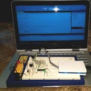
Step 3: Open a New Solution and Initiate the Programmer

Figure 6: In ‘Files > New Project’ select GCC C++ Executable Project. Figure 7: In ‘Project > Atmel Lifeline Properties’ set the programmer and the ISP Clock. Figure 8: In ‘Tools > Device Programming’ set the programmer, read the device signature and set the ISP Clock.
Although we won’t be writing code for this Instructable, we do need to make brief mention of the languages since we will open a coding [13] window which will be used in the next couple Instructables that do start coding. A number of languages can be used with the Atmel MCUs although a suitable compiler will be required to translate the English-like text into the hex/machine code used by the MCU. As a note, many modern high level languages for Windows-based systems compile to Common Intermediate Language CIL and save in that format as part of a manifest. The CIL compiles to machine code at run time [14]. We use C or C++ packed with the Atmel Studio although BASCOM [15], which is a form of BASIC, represents a strong easy-to-use competitor. The Atmel Studio 6 (AS6) provides an opportunity to choose between C or C++. We use C++ because of its similarity to C and its improved feature set. As a note, the AS6 Integrated Development Environment (IDE) is essentially the same as for Microsoft Visual Studio (VS) in terms of layout. The two IDEs (VS and AS) refer to the group of files associated with the program as the ‘solution’ and this group includes the C or C++ text file. The first link in reference [7] provides a good introduction to AS but uses a different programmer than the one used here.
Connect the programmer to the USB port.
Start Atmel Studio 6 (AS6)
Open a new solution (i.e., project) by clicking the menu sequence Files > New Project.
Complete the dialog that pops up as follows
Select the language as either C-Executable or C++Executable. We use C++ as shown in Figure 6.
Next to ‘name’ type ‘Atmel Lifeline’. AS6 will automatically complete the ‘Solution Name’.
Check the box next to ‘Create Director for Solution’.
The Device Selection Dialog pops up. Select ‘ATTiny 2313A’. Click OK.
On the menu strip at the top of AS6 window, select Project > Atmel Lifeline Properties.
On the left side of the dialog, select the Device tab and verify Device = ATTiny2313A.
On the left side of the dialog, select the Tool tab and select your programmer (Atmel ICE or AVRISP MKII etc.) in drop down box as shown in Figure 7. The ISP Clock of 125 kHz will work – this value must match the one set in Tools (Item 8) and it must be less that ¼ of the clock rate of the MCU to be programmed. In our case, the MCU will operate at 8MHz. Click the menu item File > Save all.
Connect the 9V battery to circuit and connect the programmer to the board through the adapter cable previously constructed.
On the menu strip at the top of the AS6 window, select Tools > Device Programming. In the resulting dialog shown in Figure 8, the Tool box should show your programmer (either Atmel ICE or AVRISP MKII etc.), the device should be ATTiny2313A, and the acronym ISP should be in the 3 rd box. Click APPLY. At this point, let AS6 upgrade the flash on the programmer if so requested. Refer back to Startup #1 Step 4 if the programmer did not correctly install the hardware update. Read the Target Volts – it should be within a few percent of 5V. Set the ISP Clock to 125 kHz to match that in Item 6 above. Several OKs will appear on the lower left side of the dialog.
Save the full solution. Note: The full solution can be saved by clicking the icon with the multiple disks in the tool bar or else use File > Save All.
IMPORTANT NOTE: Always make sure the ISP Clock in the Properties dialog (Item 6) matches that in the Tools section (Item 8) when opening an existing solution in Atmel Studio (after the circuit and programmer have been connected).
Do not continue if something did not properly work – check problems on the internet. If everything seems ok then Do Not shut down the AS6 dialog for Tools > Device Programming. Do not disconnect the battery.
Step 4: Fuse Selection for the ATTiny 2313A
The first programming task consists of setting the fuse bits that provide the characteristics of the MCU such as the clock source and clock divider. At the outset of most projects, you will need to decide on whether to use the internal clock source or use an external crystal with two 22pf capacitors. The internal oscillator cuts down the parts count but provides poor timing accuracy of 3%-10% as calibrated at the factory for low-precision timing applications; however, the internal oscillator can be calibrated to 1% as described in Atmel Application Note #AVR053 [16,17]. The internal oscillator would not generally be suitable for the USART serial ports. For Blinky and the Lifeline, the clock doesn’t need to be accurate but we do want the number of parts to be minimal. So we will use the internal 8MHz clock.
Complete the steps above, connect the battery to the prototype on the experimenter’s board and connect the programmer to the adapter cable and to the USB (if not already all connected). The ‘Tools > Device Programming’ dialog should be open. From the menu on the left side, select the Fuse tab.
Careful with what you do!! Some fuse settings can kill (i.e., brick) the MCU. Sometimes the fuse can be reset by building or buying High Voltage programmers (12V) as discussed in Startup #5. Check or uncheck the fuse items according to the following list and then close the Device Programming Dialog. Save and close the solution. Note: The full solution can be saved by clicking the icon with the multiple disks in the tool bar or else use File > Save All.
Table 1: Fuse settings and functions
Fuse Name | State | Description |
SELFPRGEN | NO CHECK | Similar to SPM – Do not touch! |
DWEN | NO CHECK | Debug Wire Enable – Do not touch! Enables the DebugWire interface that uses the Reset pin and overrides the SPI interface. A simplified JTAG. |
EESAVE | NO CHECK | EEProm Save: Prevents the EEProm from erasing during an MCU erase event. |
SPIEN | CHECKED | Serial Programming Interface Enable – Do not touch! This must be enabled in order to use the Atmel programmer (or compatible). Uncheck it and the MCU will not be programmable! |
WDTON | NO CHECK | Watch Dog timer: An independent timer used to reset the MCU in case the MCU stops properly functioning. The WD timer counts down to zero and will reset the MCU unless the WD timer is first reset by the program. |
BODLEVEL | DISABLED | Brown Out Detection Level: The MCU monitors the supply voltage and enters reset mode to prevent unpredictable operation when the supply voltage drops below the stated value. For 5V operation, one would use 4V3=4.3 volts |
RSTDSBL | NO CHECK | Reset Disable – Do not touch! If enabled, the reset pin will no longer reset the MCU. The programmer must be able to use the reset pin; consequently if enabled, the MCU cannot be programmed! |
CKDIV8 | NO CHECK | Clock Divide by 8: The clock rate will be decreased by a factor of 8. |
CKOUT | NO CHECK | Clock Out: Sends the clock signal to pin 6 on the ATTiny 2313A MCU |
SUT_CKSEL | INTRCOSC_8MHz_ 14CK_0MS | Setup Timer and Clock Selection (a.k.a, CKSEL) The clock source will be the internal oscillator running at 8MHz. The MCU will delay starting for 14 clock cycles and 0 milliseconds in order for the clock source to stabilize. |
A few notes on fuses:
Please set your fuses as listed in Table 1 since these settings have been tested. Problems with choosing the wrong settings for CKSEL and CKDIV8 are the ones solved by the Lifeline but that’s not built yet. The SUT_CKSEL offers a variety of clock sources but the details of each can vary from one to the next MCU type. Generally, Atmel MCUs support four broad categories of clock sources [18,19].
External Oscillator: A crystal with two 22pF capacitors. This is the most accurate clock. The crystal will often be denoted by XAL, XTAL, or X. The crystals for Atmel AVR MCUs generally range up to 20MHz.
External Clock: A module that produces the clock signal. It generally contains a crystal along with other components for precision timing.
Internal RC (a.k.a., internal oscillator): Uses a resistor and capacitor included in the MCU for timing. While the internal RC represents the simplest possible configuration that does not require external parts, it has poor factory calibrated accuracy of 3% to 10%.
External RC: Uses an external Capacitor for timing.
The ATTiny 2313A fuse SUT_CKSEL has options labeled by
INTRCOSC xMHz
The INTRCOSC refers to the Internal RC clock supplied by Atmel and the x in xMHz can be selected as 4 or 8 (etc). We will use the 8MHz setting.
EXTXOSC xMHz-yMHz
The EXTXOSC refers to a crystal oscillator (a.k.a., External Oscillator) and the range xMHz-yMHz should be selected that includes the frequency of the actual crystal placed in the circuit. The speed of Atmel MCUs can be 20MHz but the maximum rate depends on the voltage applied to the MCU – refer to the specifications on the first page or two of the manual [1].
EXTCLK
The EXTCLK option refers to a ready-made clock module suitable for producing a clock for the Atmel MCU. The module would need to have compatible output voltage and frequency.
Some options have suffix options such as 14CK_64MS. These refer to the number of clock cycles and milliseconds delay until the processor starts in order for the clock source to stabilize. Most advisors suggest using the longest delay possible although some settings appear to interfere with the program execution.
As mentioned, the maximum useable clock rate for an MCU depends on the voltage source applied between Vcc and Grnd (pins 20 and 10, respectively for ATTiny2313A). The first page of the user manual [1] for that MCU shows the speed grade list:
Table 2: Speed Grades
0 – 4 MHz @ 1.8 – 5.5V
0 – 10 MHz @ 2.7 – 5.5V
0 – 20 MHz @ 4.5 – 5.5V
The lifeline, for example in Startup #5, uses three AA batteries that can have total voltage ranging 3 to 4.9. The specifications show that the ATTiny2313A can operate up to 10MHz for this range of voltage. So, since we will keep the voltage in the range of 2.7-5.5V and we plan to use the internal oscillator, select the value of ‘INTRCOSC_8MHz’ for the SUT_CLKSEL fuse. In anticipation of constructing the Lifeline, choose the entry having the suffix of 14CK_0MS. After Lifeline has been completed, the various other clock options for a spare MCU can be tried without worrying about making that MCU nonprogrammable.
Other Atmel MCUs have other SUT_CKSEL options. For example, the ATMega328 (popular for Arduino) offers
EXTCLK – External Clock Module:
A module that produces the clock signal. It generally contains a crystal along with other components for precision timing.
INTRCOSC – Internal RC oscillator
Uses a resistor and capacitor included in the MCU for timing – poor accuracy.
EXTLOFXTAL – External Low Frequency Crystal
The MCU can use a watch crystal operating at 32.768 kHz.
EXTFSXTAL – External Full Swing Crystal
The crystal circuitry produces the maximum amplitude voltage swing for the implemented MCU voltage supply. This mode can be used to power other components that require the clock but it requires more power than the EXTXOSC mode.
EXTXOSC – External Crystal Oscillator
The EXTXOSC uses minimal power and represents the preferred mode of operation.
Regarding the BODLEVEL fuse, most Atmel MCUs like the ATTiny2313A have brown out detection (the chip will enter reset mode when the voltage falls below a set level). Normally, for 5V operation, the BODLEVEL would be 4v3=4.3V to prevent the MCU from acting erratically if/when the voltage drops below 4.3V. In particular, look at the specifications for the ATTiny2313A in the manual [1]. Look at the operating voltages (see Table 2 above). We will run the 8MHz internal oscillator. The chip can function at that rate for any voltage between 2.7 and 5.5V. For the Lifeline, our 3 AA batteries will produce voltage minimum of 3V (essentially dead) to approximately 4.9V (new). We won’t need the BODLEVEL.
Step 5: Parts List
Generally, the electronic parts can be ordered from major distributors such as DigiKey.com, Mouser.com, and Newark.com to name a few. However, interestingly, Amazon.com also provides quite the range of electronic components now while offering the possibility of 2 day shipping with Amazon Prime. Similarly, DigiKey can deliver within two days by choosing the USPS Priority Mail. Great deals can be found on Ebay but with longer shipping times in some cases.
Generally, the parts should be capable of ‘through hole’ mounting in order to be used with the experimenter’s breadboard. If you have not done so already, consider purchasing several of each in order to (i) have backup in case of an accident, (ii) lower prices for larger orders, (iii) build up a stock of parts and (iv) have parts for both a breadboard version and a finished version.
Atmel Programmer: ATATMEL-ICE-BASIC at Mouser.com or Digikey.com for about $55. The AVRISP mkII will work although it has been discontinued at Atmel. Digikey offers an Olimex unit AVR-ISP-mk2 for $28 claimed to be compatible with AS6.
Atmel Studio AS6 (free): http://www.atmel.com/tools/atmelstudio.aspx
ATTiny 2313A: Digikey.com ATTINY2313A-PU-ND at $1.70. This will be and should be the version of the ATTiny 2313A in the pDIP package (0.3” row spacing) with 20 pins. By the way, the ATTiny2313 (without the A) will also work for this project but it is considered older technology and more expensive which helps to phase it out.
Startup #5: 20 pin socket, low profile: Digikey.com ED3054-5-ND or AE9998-ND for about 30cents. Note the notch to define the end of the IC with pins 1 and 20. Similar sockets can be found on Amazon.com. We don’t need it till Startup #5 but might as well purchase it now.
LM7805 Regulator: Digikey.com LM7805CT-ND or LM7806ACT-ND for about 70Cents.
Electrolytic Capacitor 10uF, 50V: A large variety of capacitors but aluminum type will work ok:
Digikey.com: P997-ND (mfr. number: Panasonic ECE-A1HKS100) about 30cents. Actually Amazon has a capacitor kit with both ceramic and electrolytic for $20 called “Joe Knows Electronics 33 Value 645 Piece Capacitor Kit” which looks like a reasonable set.
Ceramic Capacitor 0.1uF 50V: Again, a large variety available here. Digikey.com 399-4454-1-ND (Kemet C410C104M5U5TA7200) for about 25cents. See also the kit listed in #6 above.
Optional for Startup #3: Two Ceramic Capacitors 22pF 50V from Digikey.com 490-8663-ND at 34 cents ea. Just about any 22pF capacitor will work so long as the working voltage is above the operating voltage of the MCU. These are used with a crystal.
Optional for Startup #3: Purchase a 16MHz or 20MHz crystal from the HC-49US series or a series with a similar profile. Capacitance loads in the range 18-22pF more or less and less than about 50 Ohm equivalent series resistance ESR will work ok. Amazon has nice packages of crystals as found by searching Amazon for 16MHz Crystal or 8MHz Crystal etc. Be sure to have two 22pf capacitors on hand. Here are some from Digikey.com:
16MHz Crystal from Digikey 300-6034-ND at 54cents each.
20MHz Crystal from Digikey 300-6042-ND at 54cents each.
8MHz:
8MHz Crystal from Digikey X164-ND or X1093-ND at 81cents each (but ESR=80).
8MHz Crystal from Digikey X100-ND 70cents each (but larger profile)
Amazon.com: Search 8MHz Crystal – good selection, low profile, good ESR
10MHz Crystal from Digikey 887-1010-ND at 33 cents each.
LED: Take your pick here with many sources and styles. Amazon has a package of 50 LEDs of various colors for $10 but you might need to adjust the series resistor for brightness (see Microtivity IL 185). Ebay has many.
Resistor: Schematic requires 2.2k for the LED but consider purchasing the following to adjust brightness and other uses (these are standard values). All can be 1/4 Watt. As a matter of fact, search Amazon.com for ‘resistor kit’. The SparkFun 500 1/4W resistor kit and the E-Projects – 400 Piece, 16 Value resistor kit look OK but you will likely need an Ohm meter or good color vision to read the values. Here are the values listed for Digikey:
1K Digikey.com: CF14JT1K00CT-ND 10cents each
1.5k Digikey.com: CF14JT1K50CT-ND 10cents each
2.2k Digikey.com: CF14JT2K20CT-ND 10cents each
2.7k Digikey.com: CF14JT2K70CT-ND 10cents each
3.3k Digikey.com: CF14JT3K30CT-ND 10cents each
4.7k Digikey.com: CF14JT4K70CT-ND 10cents each
5.6k Digikey.com: CF14JT5K60CT-ND 10cents each
Resistor 10k required for the RST and 1k for using Lifeline with 3.3V.
1k Digikey.com: CF14JT1K00CT-ND 10cents each
10k Digikey.com: CF14JT10K0CT-ND 10cents each
9v Battery clip: Radio Shack or search amazon.com for ‘9v battery clip’ (10 for $2).
Digikey.com: BS6I-ND 60 cents.
Optional for Startup #4: Photo-transistor. Order from either Digikey.com or Amazon.com
Digikey: Everlight PT334-6C 38cents each
Amazon: Search ‘Everlight PT334-6C’ about $5 for ten.
Optional for Startup #4: Photo-resistor from Amazon. Just about any will work ok.
Amazon.com search for ‘photoresistor GM5539’. Cost $5 for ten.
Digikey PDV-P8001-ND by Advanced Photonics mfg # PDV-P8001 for $2.22
The plastic housing for the Lifeline is constructed from a battery holder for 4 AA batteries that also has a switch. These come from Radio Shack or Amazon.com. For amazon, search for ‘plastic battery holder 4 AA switch’. Make sure the case holds 4 AA batteries and has a switch. I found a deal of five cases for $8.
Experimenter’s breadboard: There are many types and sizes and places to purchase.
Amazon.com: MB-102 Point Prototype PCB breadboard for $5 includes wires
Amazon.com: MB-102 830 Solderless Breadboard for $4 with wires.
8-32 screw 1.5” long. Check HomeDepot.com or Lowes.com. Any 8-32” screw longer than 2” will be ok so long as it is later cut to a length of 1.5”. You need two 8-32 nuts. Many times the 8-32 screws come with either a large flat head (truss head) or the smaller round heads (round head). Find the round head since these fit better with the spring. The truss head would likely need to be filed down.
24 gauge solid core copper wire. For Startup #2, if you have the premade wires for the experimenter’s breadboard then you won’t need this wire for this Startup. I have been using old telephone wire and intercom wire that I have either found or purchased at Radio Shack. I especially like this wire because of the many colors, it can be cut to any length, and the diameter nicely fits the experimenter’s boards. The 24ga has a diameter of approximately 0.51 mm but it’s not critical. The 26ga should work ok even though the diameter is about 0.45mm. The outside plastic must be cut off to access the various colored inner wires. Amazon.com: search on ‘4 conductor 24 awg cable solid copper’ either 60cents/foot or $20 for 100 feet. Ebay.com has nice 24 ga. solid core wire with multicolors. Search: ‘solid 24 gauge wire kit’. Home Depot: 100 ft. 6-conductor Indoor Phone wire for $20. I have not checked this for solid core copper. For soldering the ICs and components, you might want to use 24ga stranded copper wire since it is more flexible and less likely to pull loose from the joint. Amazon.com: search for ‘24 gauge stranded wire’. Nice 6 spool kits (150’ total) will come up for $20.
Step 6: Reference
[0] The Atmel Startup articles, Instructables.com, 2015, M. A. Parker, Angstrom Logic:
A. Atmel Startup 1: Atmel Studio and Programmer
B. Atmel Startup 2: Microcontroller Circuits and Fuses
C. Atmel Startup 3: Blinky One – PORT, PIN, DDR and LED
D. Atmel Startup 4: Blinky Two – Switches, Pull-Up Resistor, and Bit Ops
E. Atmel Startup 5: Lifeline
As a note, these Instructables made extensive use of the free HTML conversion tool at http://word2cleanhtml.com/ by cutting and pasting into the tool and then cutting and pasting the results into the Instructables page using the HTML view.
[1] The complete Atmel manual for the ATTiny 2313A: http://www.atmel.com/Images/doc8246.pdf. Don’t worry about its rather large size, a few simple ‘tricks’ will get you started. More information on the ATTiny2313A can be found at http://www.atmel.com/devices/ATTiny2313A.aspx.
[2] Arduino products and learning: http://www.arduino.cc/
[3] Raspberry Pi products and learning: https://www.raspberrypi.org/
[4] A good selection of tutorials here:
https://www.newbiehack.com/MicrocontrollerIntroductionABeginnersGuidetotheAtmelAVRAtmega32.aspx
[5] Without a doubt, visit avrfreaks.net for tutorials as well as project help
http://www.avrfreaks.net/forum/newbie-start-here?name=PNphpBB2&file=viewtopic&t=70673
http://www.avrfreaks.net/forums/tutorials?name=PNphpBB2&file=viewforum&f=11
[6] The SparkFun website has a variety of tutorials ranging from electronics to software:
https://learn.sparkfun.com/tutorials/tags/concepts
[7] A couple of very worthwhile tutorials can be found on Instructables.com. The following link has a very good intro to AS and fuses, but uses different programmer
The tutorial from the following link uses a different development environment and programmer.
https://www.instructables.com/id/Getting-Started-with-Embedded-Systems-using-Atmel/
[8] Adafruit.net provides information as well as a great place to purchase very affordable microcontroller components https://learn.adafruit.com/.
[9] ATTiny tutorial listed on right hand side: http://startingelectronics.org/tutorials/
[10] Links for information regarding Experimenter’s Breadboards.
https://www.youtube.com/watch?v=1sGcL5Eeaeo
http://computers.tutsplus.com/tutorials/how-to-use-a-breadboard-and-build-a-led-circuit--mac-54746
https://www.instructables.com/id/How-to-use-a-breadboard/
[11] Capacitor codes: http://www.wikihow.com/Read-a-Capacitor
[12] Resistor color code https://en.wikipedia.org/?title=Electronic_color_code
[13] Coding vs. Programming http://workfunc.com/differences-between-programmers-and-coders/
[14] https://en.wikipedia.org/wiki/Common_Intermediate_Language
[15] Bascom: http://mcselec.com/index.php?option=com_content&task=view&id=14&Itemid=41
[16] Calibration of the internal RC Oscillator (AVR053): http://www.atmel.com/images/doc2555.pdf
[17] J. Pardue, “C Programming for Microcontrollers Featuring ATMEL’s AVR Butterfly and the free WinAVR Compiler”, Published by Smiley Micros (2005). ISBN: 0976682206. Amazon.com
[18] Clock sources described for Atmega168 https://www.sparkfun.com/tutorials/95
[19] Useful fuse information
http://www.scienceprog.com/programming-avr-fuse-bits-oscillator-settings/
http://www.ladyada.net/learn/avr/fuses.html
https://embedderslife.wordpress.com/2012/08/20/fuse-bits-arent-that-scary
[20] Notes on crystals:


