Build a Solar Powered ESP8266
Intro: Build a Solar Powered ESP8266
In this Instructable we are showing how to build a solar powered ESP8266
We connect up an ESP8266 to the SunAirPlus Solar Power Controller/Charger/Data Collection board and to a solar panel/battery.
The purpose of this project is five fold:
- Demonstrate ESP8266 on Solar Power
- Measure EPS8266 power consumption dynamically
- Show how to use a REST interface to send to a database on a Raspberry Pi
- Display the data on the Raspberry Pi on graphs using MatPlotLib
- Adding a stepper motor to the solar panel to track the sun (next project) and measure the results versus non-tracking
For this project, we are using an Adafruit Huzzah ESP8266 WiFi/processor connected up to a SwitchDoc Labs SunAirPlus solar power controller/charger/data collector.
In this instructable you will learn the following:
- How to hook up an ESP8266 to a solar power controller, SunAirPlus
- How to Program an ESP8266 using the Arduino IDE
- How to communicate over the I2C bus on the ESP8266
- Learn to read 3 current/voltage sensors on SunAirPlus - Battery, Panels and Load
- How to build a REST interface so you can communicate with the ESP8266 via a web browser or computer
This project is suitable for STEM projects for late middle school and above.
Visit www.switchdoc.com for more IOT, Solar Power and ESP8266 postings.
STEP 1: What Are We Using for This Project?
The ESP8266
The ESP8266 is made by a privately held company in China called Espressif. They are a fabless semiconductor company that just came out of nowhere and shook up the whole industry. Now all the major players are working on inexpensive versions of an IOT chip with WiFi connectivity. And they are all struggling to make it as inexpensive as the ESP8266
The Adafruit ESP8266 Huzzah
The Adafruit ESP8266 Huzzah board is a great breakout for the ESP8266. It makes it much easier to use than the really cheap modules. Most of the low cost modules are not breadboard friendly, don't have an onboard 3.3V regulator or level shifting for signals. The Huzzah has all of those features. For more on the ESP8266 Huzzah board see this posting.
SwitchDoc Labs SunAirPlus Solar Power Controller/Charger/Data Collector SunAirPlus is a 3rd Generation Solar Charging and Sun Tracking Board designed by and manufactured by SwitchDoc Labs.
You can use this board to power your projects and add a servo or stepper motor to allow it to track the sun using photoresistors to generate even more power. It incorporates a number of outstanding features in a very compact, inexpensive single fully assembled and tested PC Board. SunAirPlus is customizable with your software and hardware.
The ESP8266 Software
We are using the Arduino IDE for this project. See how to use the Arduino IDE with the ESP8266 in this posting.
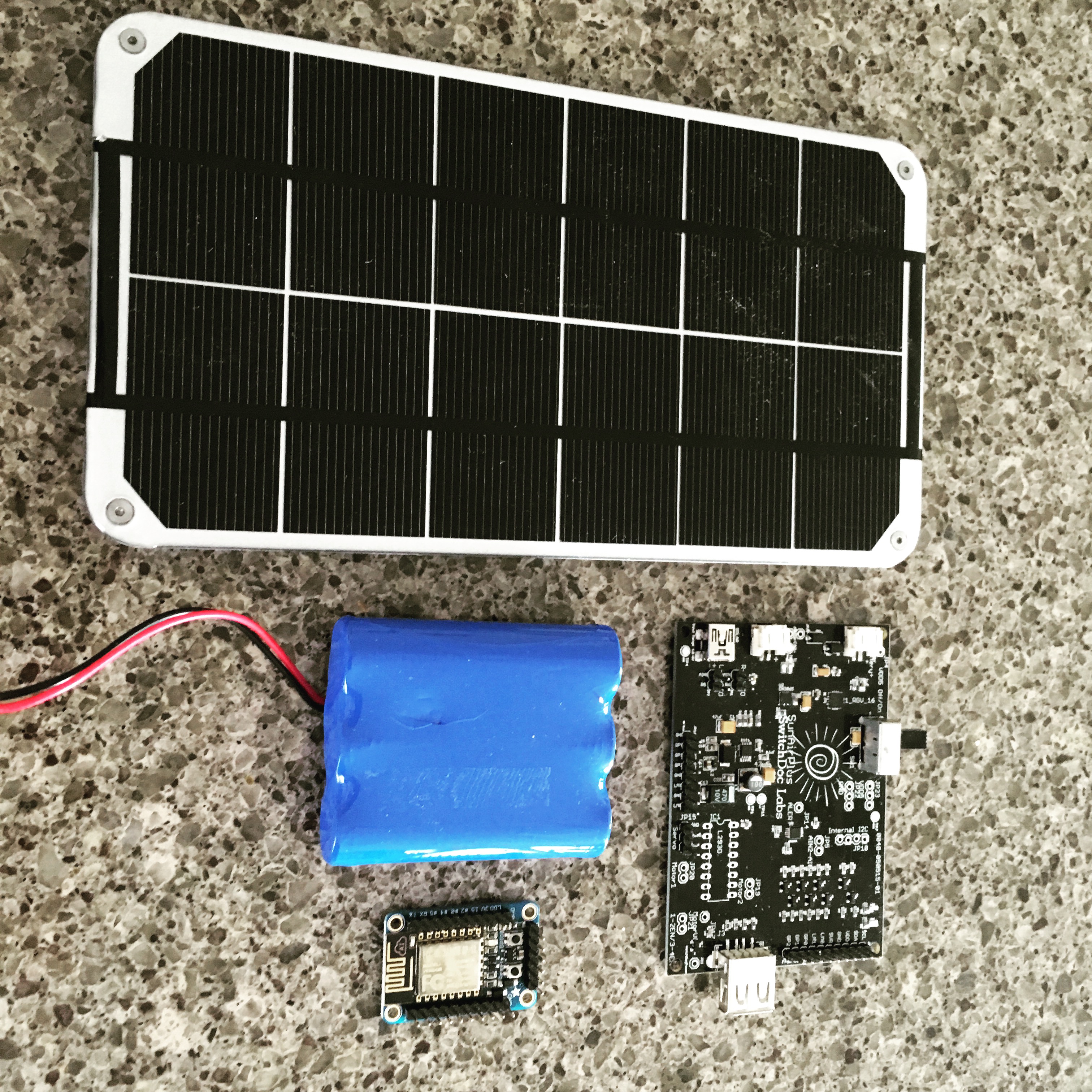
STEP 2: The Block Diagram
SolarPowerESP8266 is an IOT system built by SwitchDoc Labs for an upcoming article on building IOT devices. It consists of five major pieces:
- ESP8266 Huzzah WiFi/CPU (programmed in Arduino IDE)
- SunAirPlus - Solar Power Controller/Charger Data Collector
- LiPo Battery
- 6V 3.4W Solar Panel
- Raspberry Pi as Data Logger / Analytics / Display
The system works as follows: SunAirPlus is hooked up to a solar panel and a LiPo battery. SunAirPlus handles all the complexities of properly charging and discharging a LiPo battery. It also supplies 5V to the ESP8266. SunAirPlus also contains an INA3221 3 channel current and voltage sensor. It reads current and voltage from the battery, the solar panel and the voltage and current going to the load (the ESP8266). It allows you to see exactly what is going on in your solar panel system. More data the better, we say at SwitchDoc Labs. The ESP8266 is connected to the 5V power supply from SunAirPlus (SunAirPlus is smart enough to take power from whatever is hooked up to it, either from the battery, the USB Power connector or from the Solar Panel) and the ESP8266 is connected up to the I2C bus on SunAirPlus. SunAirPlus handles the translation from the 3.3V I2C bus from the ESP8266 to the internal 5V I2C bus of SunAirPlus.
STEP 3: Serial Output From the SolarPowerESP8266
----------------
SolarPower ESP8266
----------------
Connec.......
Local WiFi connected, IP address: 192.168.1.129
Server started
Free heap on ESP8266:33080

--------SAP Data-------
LIPO_Battery Bus Voltage: 4.06 V
LIPO_Battery Load Voltage: 4.07 V
LIPO_Battery Current: 113.20 mA

Solar Cell Bus Voltage: 3.63 V
Solar Cell Load Voltage: 3.63 V
Solar Cell Current: 0.00 mA

Output Bus Bus Voltage: 4.98 V
Output Bus Load Voltage: 4.99 V
Output Bus Current: 92.00 mA

--------
Free heap on ESP8266:33080

--------SAP Data-------
LIPO_Battery Bus Voltage: 4.06 V
LIPO_Battery Load Voltage: 4.07 V
LIPO_Battery Current: 114.80 mA

Solar Cell Bus Voltage: 3.62 V
Solar Cell Load Voltage: 3.62 V
Solar Cell Current: 0.00 mA

Output Bus Bus Voltage: 4.98 V
Output Bus Load Voltage: 4.99 V
Output Bus Current: 88.80 mA

--------
--------
Buffer Count=9
Request received
GET /
RestDataString HTTP/
Sending command
Command: s
State: x
State of buffer at the start:
Added to buffer: RestDataString
Added to buffer: 32696 | 32523,4.05,4.06,131.20,3.62,3.62,0.00,4.98,4.99,104.00 | 33538,4.05,4.06,132.40,3.62,3.62,0.00,4.98,4.99,102.00 | 34554,4.05,4.06,131.20,3.62,3.62,0.00,4.98,4.99,102.40 | 35570,4.05,4.06,131.60,3.62,3.62,0.00,4.98,4.99,102.40 | 36586,4.05,4.06,131.20,3.62,3.62,0.00,4.98,4.99,102.40 | 37602,4.05,4.06,131.60,3.62,3.62,0.00,4.98,4.99,110.00 | 38618,4.05,4.06,133.20,3.62,3.62,0.00,4.98,4.99,102.00 | 39634,4.05,4.06,132.00,3.62,3.62,0.00,4.98,4.99,102.00 | 40650,4.05,4.06,130.80,3.62,3.62,0.00,4.98,4.99,102.00
Added to buffer: 1
Added to buffer: SolarPowerESP8266
State of buffer at the end: HTTP/1.1 200 OK
Access-Control-Allow-Origin: *
Access-Control-Allow-Methods: POST, GET, PUT, OPTIONS
Content-Type: application/json
Connection: close
{"RestDataString": "32696 | 32523,4.05,4.06,131.20,3.62,3.62,0.00,4.98,4.99,104.00 | 33538,4.05,4.06,132.40,3.62,3.62,0.00,4.98,4.99,102.00 | 34554,4.05,4.06,131.20,3.62,3.62,0.00,4.98,4.99,102.40 | 35570,4.05,4.06,131.60,3.62,3.62,0.00,4.98,4.99,102.40 | 36586,4.05,4.06,131.20,3.62,3.62,0.00,4.98,4.99,102.40 | 37602,4.05,4.06,131.60,3.62,3.62,0.00,4.98,4.99,110.00 | 38618,4.05,4.06,133.20,3.62,3.62,0.00,4.98,4.99,102.00 | 39634,4.05,4.06,132.00,3.62,3.62,0.00,4.98,4.99,102.00 | 40650,4.05,4.06,130.80,3.62,3.62,0.00,4.98,4.99,102.00", "id": "1", "name": "SolarPowerESP8266", "connected": true}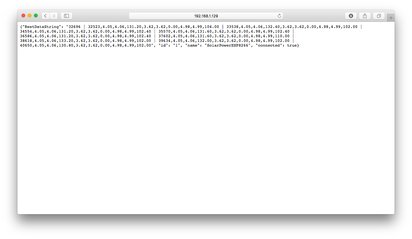
STEP 4: Parts List
PartDescriptionSourcePriceLink ESP8266ESP8266 Huzzah Breakout BoardAdafruit~$10https://www.adafruit.com/products/2471 SunAIrPlusSolar Power Controller / Charger / Data CollectorSwitchDoc Labs~$45http://www.switchdoc.com/?p=1332 6500 mAh LiPo BatteryRechargeable LiPo BatteryAdafruit~$30https://www.adafruit.com/products/353 FTDI CableCable for programming from PC or MacSwitchDoc Labs~$13http://www.switchdoc.com/?p=2868 6V 3.5W Solar PanelSolar Panel to connect to SunAIrPlusVoltaics System~$39http://www.voltaicsystems.com/3-5-watt-panel
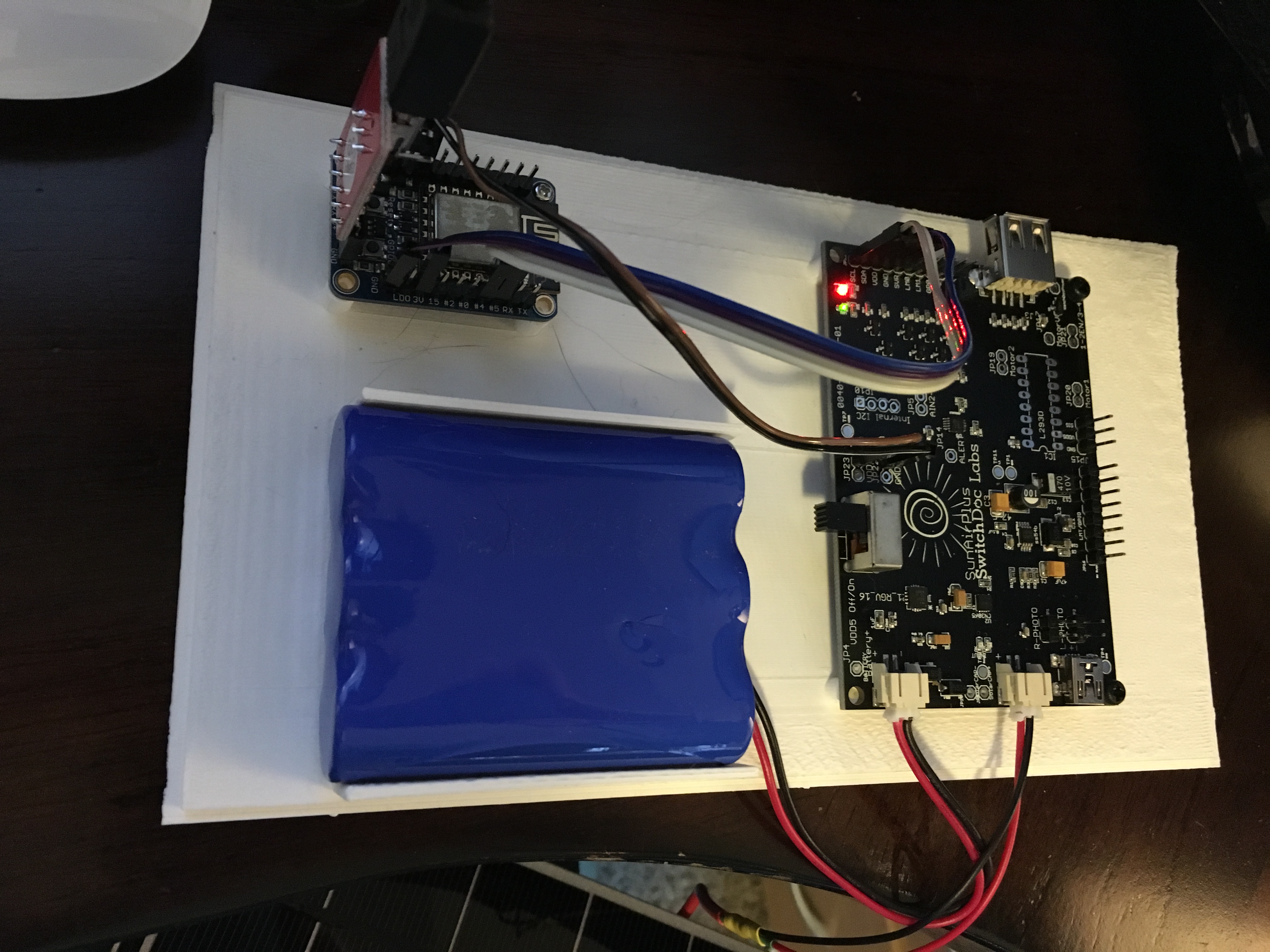
STEP 5: Wiring List
The wiring list for this project is below:
Key:ESP8266 Huzzah Board: ESP8266 SunAirPlus Solar Panel Controller/Charger/Data Collector: SunAirPlus LiPo Battery: Battery Solar Panel: Solar Panel FromToDescriptionFromToDescriptionESP8266 Huzzah Board ESP8266 / GNDSunAIrPlus/JP13-4/GNDGround ESP8266 / 3VSunAIrPlus/JP13-3/3V33.3V power SunAirPlus InterfaceESP8266 / #4SunAIrPlus/JP13-2/SDASDA for I2C SunAirPlus InterfaceESP8266 / #5SunAIrPlus/JP13-1/SCLSCL for I2C SunAirPlus InterfaceESP8266 / GNDSunAirPlus/JP22-1/GNDGND for ESP8266ESP8266 / V+SunAirPlus/JP23-1/VDD55 V supply for ESP8266 SunAirPlus board SunAirPlus/J5/BatteryJST2 Plug on LiPo Battery SunAirPlus/J6/SolarPanelJST2 Plug from Solar PanelFTDI Cable Plugged in Correctly
An FTDI cable is plugged into the end of the Adafruit Huzzah ESP8266. Make sure you align the black wire with the GND pin on the ESP8266 breakout board as shown below. SwitchDoc Labs has an inexpensive one available here. The Voltaics Panel comes with a 1.3mm barrel plug. If you don't want to cut it off and solder a JST2 plug onto the connector, you can buy these two adaptors: 1.33mm plug to 2.1mm barrel plug adaptor and a 2.1mm barrel plug to JST2 adaptor. Be careful in plugging in the FTDI Cable. Align GND with GND on the ESP8266 board as in the picture to the right.
STEP 6: Results
The results from the ESP8266 REST interface are formatted as a JSON string. The below JSON strings are in response to the following browser command:
http://192.168.1.129/RestDataString/The data string contains data, each packet of data delimited by a "|" character. The first value (38160) is the current value of the free heap (RAM available) on the ESP8266. It's put there to help monitor memory leaks, which we were initially concerted about. However, the latest version of the Arduino IDE ESP8266 SDK is doing a lot better. The next two packets are the data from SunAirPlus, formatted as follows:
<timestamp - milliseconds since ESP8266 boot >, <LIPO_Battery Bus Voltage(V)>, <LIPO_Battery Load Voltage(V)>, <LIPO_Battery Current(mA)>, <Solar Cell Bus Voltage(V)>, <Solar Cell Load Voltage(V)>, <Solar Cell Current(mA)>, <Output Bus Bus Voltage(V)>, <Output Bus Load Voltage(V)>, <Output Bus Current(mA)>
The important values are those that say "Load Voltage" and "Current". Output Bus refers to the current going into the ESP8266.
The values in the string below are: 4.08V for the LiPo Battery, 3.53V for the Solar Cell and 4.98V for the Voltage supply to the ESP8266.
The REST respond below was taken with the Load Power Switch (SW1 - Turn off Voltage Booter) OFF. This makes the current values look funny as the ESP8266 is being powered through the connected FTDI cable.{"RestDataString": "38160 | 4684697,4.08,4.08,0.00,3.53,3.53,0.00,4.98,4.98,-0.40 | 4685720,4.08,4.08,0.00,3.53,3.53,0.00,4.98,4.98,-0.40", "id": "1", "name": "SolarPowerESP8266", "connected": true}
{"RestDataString": "37968 | 4707212,4.07,4.08,40.00,3.53,3.53,0.00,5.00,5.00,29.60 | 4708235,4.07,4.08,42.80,3.53,3.53,0.00,5.00,5.00,29.60 | 4709259,4.07,4.08,42.00,3.53,3.53,0.00,5.00,5.00,29.60 | 4710283,4.07,4.08,44.80,3.53,3.53,0.00,5.00,5.00,29.60 | 4701072,4.08,4.08,0.00,3.53,3.53,0.00,4.97,4.97,0.40 | 4702095,4.07,4.08,38.00,3.52,3.52,0.00,4.99,4.99,28.40 | 4703118,4.07,4.08,42.80,3.53,3.53,0.00,5.00,5.00,29.60 | 4704141,4.07,4.08,40.00,3.53,3.53,0.00,5.00,5.00,30.00 | 4705165,4.07,4.08,42.40,3.53,3.53,0.00,5.00,5.00,29.20 | 4706188,4.07,4.08,42.00,3.53,3.53,0.00,5.00,5.00,29.60", "id": "1", "name": "SolarPowerESP8266", "connected": true}
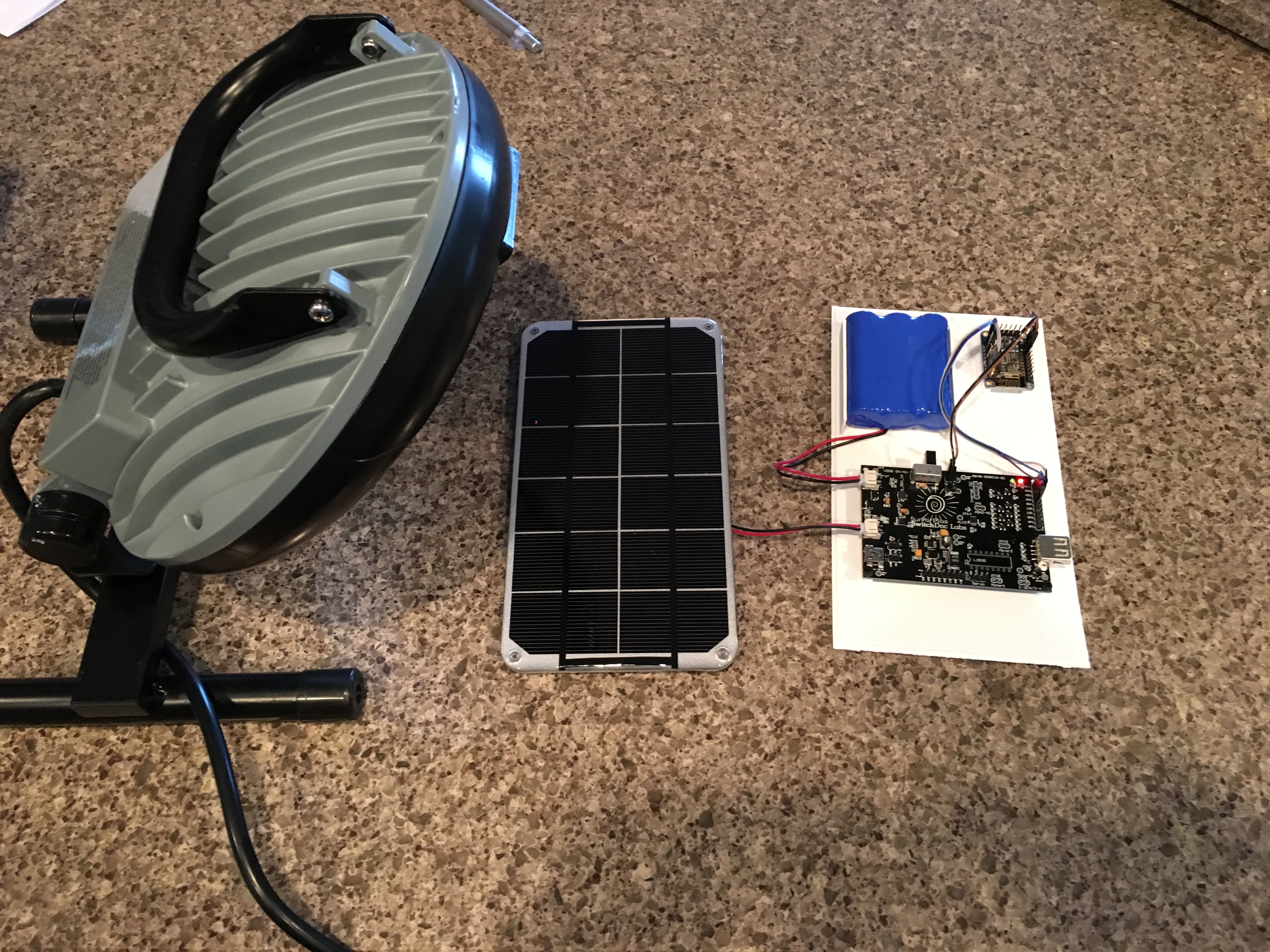
Next, we unplug the FTDI cable, have the SunAirPlus Switch ON and turn on the strong light on the solar panel. And now weare generating power from the Solar Panel. We are getting 66ma from the battery, 43ma from the solar panels and we are supplying 82ma to the ESP8266. Perfect!
{"variables": {"RestTimeStamp": 73667, "RestDataString": "38848 | 64972,4.10,4.10,66.40,4.66,4.65,43.20,4.98,4.99,82.40 | 65995,4.10,4.10,62.80,4.66,4.65,42.40,4.98,4.99,91.20 | 67019,4.10,4.10,67.20,4.66,4.65,42.40,4.98,4.99,86.00 | 68042,4.10,4.10,69.60,4.66,4.65,42.80,4.98,4.99,86.00 | 69065,4.10,4.10,63.60,4.66,4.65,43.20,4.98,4.99,97.60 | 70089,4.10,4.10,63.20,4.66,4.65,43.20,4.98,4.99,82.80 | 71112,4.10,4.10,58.00,4.66,4.65,42.80,4.98,4.99,84.40 | 72136,4.10,4.10,64.00,4.66,4.65,42.40,4.98,4.99,82.00 | 73159,4.10,4.10,64.40,4.66,4.65,43.20,4.98,4.99,82.40 | 63948,4.10,4.10,64.40,4.66,4.65,42.80,4.98,4.99,82.40"}, "id": "1", "name": "SolarPowerESP8266", "connected": true}
{"RestDataString": "39328 | 566634,4.08,4.09,107.60,3.63,3.63,0.00,4.98,4.99,90.40 | 567657,4.08,4.09,116.00,3.63,3.63,0.00,4.98,4.99,90.40 | 568683,4.08,4.09,107.60,3.63,3.63,0.00,4.98,4.99,88.80 | 569706,4.08,4.09,107.60,3.63,3.63,0.00,4.98,4.99,103.60 | 570730,4.08,4.09,107.60,3.63,3.63,0.00,4.98,4.99,96.00 | 571753,4.08,4.09,120.00,3.63,3.63,0.00,4.98,4.99,93.20 | 572777,4.08,4.09,107.60,3.63,3.63,0.00,4.98,4.99,94.40 | 573801,4.08,4.09,108.00,3.63,3.63,0.00,4.98,4.99,90.40 | 564586,4.08,4.09,131.20,3.60,3.60,0.00,4.98,4.99,90.40 | 565609,4.08,4.09,107.60,3.63,3.63,0.00,4.98,4.99,108.40", "id": "1", "name": "SolarPowerESP8266", "connected": true}STEP 7: Arduino IDE Source Code for the Project
Below is the source code for the Arduino IDE ESP8266 pack. To install the Arduino IDE ESP8266 pack check out this post.
Required libraries:
aREST.h - https://github.com/marcoschwartz/aREST
SunAirPlus INA3221 Libraries - https://github.com/switchdoclabs/SDL_Arduino_INA3221
Make sure you put in your own values for SSID and your PASSWORD for your local access point:
SolarPowerESP8266.ino/*
SwitchDoc Labs Code for SolarPower ESP8266
Uses ESP8266 and SunAirPlus
Dedember 2015
*/
#pragma GCC diagnostic ignored "-Wwrite-strings"
extern "C" {
#include "user_interface.h"
}
#include
#define DEBUG_MODE 1
#include
#include
// SunAirPlus Data Structures
// Note: SunAirPlus uses a 3 channel current/voltage I2C chip - INA3221 to read all values - see github.com/switchdoclabs/SDL_Arduino_INA3221
//
#include "SDL_Arduino_INA3221.h"
// SAP INA3221
SDL_Arduino_INA3221 ina3221_SAP;
// structure for one SAP ina3221
struct SAPData
{
float busVoltage[3];
float current[3];
float loadVoltage[3];
};
SAPData currentSAPData;
// the three channels of the INA3221 named for SunAirPlus Solar Power Controller channels (www.switchdoc.com)
#define SAP_LIPO_BATTERY_CHANNEL 0
#define SAP_SOLAR_CELL_CHANNEL 1
#define SAP_OUTPUT_CHANNEL 2
// SAP Buffer for sending readings to RaspberryPi
struct SAPBufferStruct
{
unsigned long timeStamp;
SAPData SAPEntry;
};
#define SAPBUFFERSIZE 200
SAPBufferStruct SAPBuffer[SAPBUFFERSIZE];
int CurrentSAPBuffer;
int lastReadSAPBuffer;
#include "SAPData.h"
//----------------------------------------------------------------------
//Local WiFi SunAirPlus
const char* ssid = "YOURSSID";
const char* password = "YOURPASSWORD";
#define SOLARPOWERESP8266VERSION 004
//----------------------------------------------------------------------
int blinkPin = 0; // pin to blink led at each reading
// The port to listen for incoming TCP connections
#define LISTEN_PORT 80
// Create an instance of the server
WiFiServer server(LISTEN_PORT);
unsigned long oldReadSunAirPlusTime;
unsigned long newReadSunAirPlusDeltaTime;
int RestTimeStamp;
String RestDataString;
// Create aREST instance
aREST rest = aREST();
// Custom function accessible by the API
int ledControl(String command) {
// Get state from command
int state = command.toInt();
digitalWrite(0, state);
return 1;
}
void setup() {
pinMode(blinkPin, OUTPUT); // pin that will blink every reading
digitalWrite(blinkPin, HIGH); // High of this pin is LED OFF
// SAP initialization
startSAPINA3221();
Serial.begin(115200); // we agree to talk fast!
Serial.println("----------------");
Serial.println("SolarPower ESP8266");
Serial.println("----------------");
RestTimeStamp = 0;
RestDataString = "";
rest.variable("RestTimeStamp", &RestTimeStamp);
rest.variable("RestDataString", &RestDataString);
// Function to be exposed
rest.function("led", ledControl);
// Give name and ID to device
rest.set_id("1");
rest.set_name("SolarPowerESP8266");
Serial.print("Connecting to ");
Serial.print(ssid);
if (strcmp (WiFi.SSID().c_str(), ssid) != 0) {
WiFi.begin(ssid, password);
}
while (WiFi.status() != WL_CONNECTED) {
delay(500);
Serial.print(".");
}
Serial.println("");
Serial.print("Local WiFi connected, IP address: ");
Serial.println(WiFi.localIP());
// Start the server
server.begin();
Serial.println("Server started");
oldReadSunAirPlusTime = micros();
initSAPBuffer();
}
int sampleCount = 0;
// Loop through reading current and solar performance
void loop() {
// Handle REST calls
WiFiClient client = server.available();
if (client)
{
while (!client.available()) {
delay(1);
}
if (client.available())
{
Serial.print("Buffer Count=");
Serial.println(returnCountSAPBuffer());
RestTimeStamp = millis();
//printDebugFullSAPBuffer();
RestDataString = assembleSAPBuffer();
rest.handle(client);
}
}
newReadSunAirPlusDeltaTime = micros() - oldReadSunAirPlusTime; // doing this handles the 71 second rollover because of unsighned arithmetic
if (newReadSunAirPlusDeltaTime > 1000000) // check for 1 second work to be done
{
Serial.print("Free heap on ESP8266:");
Serial.println(ESP.getFreeHeap(), DEC);
digitalWrite(blinkPin, LOW); // High of this pin is LED ON
Serial.println();
readSAP();
writeSAPBuffer();
digitalWrite(blinkPin, HIGH); // High of this pin is LED OFF
oldReadSunAirPlusTime = micros();
//printDebugFullSAPBuffer();
}
yield(); // take a break - you must do this for the ESP8266 to work correctly in all cases!
}
The file SAPData.h // SAP Buffer Routines
void initSAPBuffer()
{
CurrentSAPBuffer = -1;
lastReadSAPBuffer = -1;
int i;
for (i = 0; i < SAPBUFFERSIZE; i++) { SAPBuffer[i].timeStamp = 0; } } void writeSAPBuffer() { //Serial.print("Entry WriteSAPBuffer C / R "); //Serial.print(CurrentSAPBuffer); //Serial.print(" / "); //Serial.println(lastReadSAPBuffer); CurrentSAPBuffer++; if (CurrentSAPBuffer >= SAPBUFFERSIZE) // wrap around
{
CurrentSAPBuffer = 0;
}
SAPBuffer[CurrentSAPBuffer].timeStamp = millis();
SAPBuffer[CurrentSAPBuffer].SAPEntry = currentSAPData;
//Serial.print("Exit WriteSAPBuffer C / R ");
//Serial.print(CurrentSAPBuffer);
//Serial.print(" / ");
//Serial.println(lastReadSAPBuffer);
}
int returnCountSAPBuffer()
{
int i;
int count = 0;
for (i = 0; i < SAPBUFFERSIZE; i++) { if (SAPBuffer[i].timeStamp > 0)
count++;
}
return count;
}
int readSAPBuffer(SAPBufferStruct *mySAPBuffer)
{
//Serial.print("inReadSAPBuffer C / R ");
//Serial.print(CurrentSAPBuffer);
//Serial.print(" / ");
//Serial.println(lastReadSAPBuffer);
// read out all data, doesn't matter the order. The SQL Databoase on the Pi will figure it out...
if (lastReadSAPBuffer == -1 ) // deal with first read no matter how long ago
{
// scan Buffer for smallest > 0 timeStamp - set to lastReadSAPBuffer
int i;
int smallestTimeStamp = 4294967295; // 2^32-1
int smallestIndex = 0;
for (i = 0; i < SAPBUFFERSIZE; i++)
{
if (SAPBuffer[i].timeStamp != 0)
{
if (SAPBuffer[i].timeStamp < smallestTimeStamp) { smallestTimeStamp = SAPBuffer[i].timeStamp; smallestIndex = i; } } } lastReadSAPBuffer = smallestIndex; } if (SAPBuffer[lastReadSAPBuffer].timeStamp == 0) { return -1; } *mySAPBuffer = SAPBuffer[lastReadSAPBuffer]; SAPBuffer[lastReadSAPBuffer].timeStamp = 0; lastReadSAPBuffer++; if (lastReadSAPBuffer >= SAPBUFFERSIZE)
{
lastReadSAPBuffer = 0;
}
}
String assembleSAPBuffer()
{
int status;
SAPBufferStruct mySAPBuffer;
String returnString;
returnString = "";
returnString = String(ESP.getFreeHeap());
status = readSAPBuffer(&mySAPBuffer);
while (status != -1)
{
if (returnString.length() != 0)
{
returnString += " | ";
}
String sensorBuild;
sensorBuild = String(mySAPBuffer.timeStamp) + ",";
int i;
for (i = 0; i < 3; i++)
{
sensorBuild += String(mySAPBuffer.SAPEntry.busVoltage[i], 2) + ",";
sensorBuild += String(mySAPBuffer.SAPEntry.loadVoltage[i], 2) + ",";
if (i < 2)
sensorBuild += String(mySAPBuffer.SAPEntry.current[i], 2) + ",";
else
sensorBuild += String(mySAPBuffer.SAPEntry.current[i], 2) ;
//Serial.print("sensorBuild=");
//Serial.println(sensorBuild);
}
returnString += sensorBuild;
status = readSAPBuffer(&mySAPBuffer);
}
return returnString;
}
void printDebugFullSAPBuffer()
{
Serial.print("DebugFullSAPBuffer State C / R ");
Serial.print(CurrentSAPBuffer);
Serial.print(" / ");
Serial.println(lastReadSAPBuffer);
int i;
for (i = 0; i < SAPBUFFERSIZE; i++)
{
Serial.print("index:");
Serial.print(i);
Serial.print(" timeStamp = ");
Serial.print(SAPBuffer[i].timeStamp);
if (SAPBuffer[i].timeStamp == 0)
{
Serial.println(" SAPEntry = null");
}
else
{
Serial.println(" SAPEntry = Full");
/*
SAPData currentSAPData;
currentSAPData = SAPBuffer[i].SAPEntry;
Serial.println("--------SAP ENTRY-------");
Serial.print("LIPO_Battery Current: "); Serial.print(currentSAPData.current[0]); Serial.println(" mA");
Serial.print("Solar Cell Bus Voltage: "); Serial.print(currentSAPData.busVoltage[1]); Serial.println(" V");
Serial.print("Output Bus Current: "); Serial.print(currentSAPData.current[2]); Serial.println(" mA");
*/
}
}
}
// Read data from specific SunAirPlus unit (SAP0 - SAP2)
void startSAPINA3221()
{
ina3221_SAP.begin(); // SAP
}
void readSAP()
{
int i;
for (i = 0; i < 3; i++)
{
currentSAPData.busVoltage[i] = 0.0f;
currentSAPData.current[i] = 0.0f;
currentSAPData.loadVoltage[i] = 0.0f;
}
currentSAPData.busVoltage[0] = ina3221_SAP.getBusVoltage_V(SAP_LIPO_BATTERY_CHANNEL + 1);
currentSAPData.current[0] = ina3221_SAP.getCurrent_mA(SAP_LIPO_BATTERY_CHANNEL + 1); // minus is to get the "sense" right. - means the battery is charging, + that it is discharging
currentSAPData.loadVoltage[0] = currentSAPData.busVoltage[0] + (ina3221_SAP.getShuntVoltage_mV(SAP_LIPO_BATTERY_CHANNEL + 1) / 1000);
currentSAPData.busVoltage[1] = ina3221_SAP.getBusVoltage_V(SAP_SOLAR_CELL_CHANNEL + 1);
currentSAPData.current[1] = - ina3221_SAP.getCurrent_mA(SAP_SOLAR_CELL_CHANNEL + 1); // minus is to get the "sense" right. - means the battery is charging, + that it is discharging
currentSAPData.loadVoltage[1] = currentSAPData.busVoltage[1] + (ina3221_SAP.getShuntVoltage_mV(SAP_SOLAR_CELL_CHANNEL + 1) / 1000);
currentSAPData.busVoltage[2] = ina3221_SAP.getBusVoltage_V(SAP_OUTPUT_CHANNEL + 1);
currentSAPData.current[2] = ina3221_SAP.getCurrent_mA(SAP_OUTPUT_CHANNEL + 1); // minus is to get the "sense" right. - means the battery is charging, + that it is discharging
currentSAPData.loadVoltage[2] = currentSAPData.busVoltage[2] + (ina3221_SAP.getShuntVoltage_mV(SAP_OUTPUT_CHANNEL + 1) / 1000);
Serial.println("--------SAP Data-------");
Serial.print("LIPO_Battery Bus Voltage: "); Serial.print(currentSAPData.busVoltage[0]); Serial.println(" V");
Serial.print("LIPO_Battery Load Voltage: "); Serial.print(currentSAPData.loadVoltage[0]); Serial.println(" V");
Serial.print("LIPO_Battery Current: "); Serial.print(currentSAPData.current[0]); Serial.println(" mA");
Serial.println("");
Serial.print("Solar Cell Bus Voltage: "); Serial.print(currentSAPData.busVoltage[1]); Serial.println(" V");
Serial.print("Solar Cell Load Voltage: "); Serial.print(currentSAPData.loadVoltage[1]); Serial.println(" V");
Serial.print("Solar Cell Current: "); Serial.print(currentSAPData.current[1]); Serial.println(" mA");
Serial.println("");
Serial.print("Output Bus Bus Voltage: "); Serial.print(currentSAPData.busVoltage[2]); Serial.println(" V");
Serial.print("Output Bus Load Voltage: "); Serial.print(currentSAPData.loadVoltage[2]); Serial.println(" V");
Serial.print("Output Bus Current: "); Serial.print(currentSAPData.current[2]); Serial.println(" mA");
Serial.println("");
Serial.println("--------");
return;
}
STEP 8: Conclusion
This instructable demonstrates how to hook up an ESP8266 CPU/WiFi unit to a solar panel and communicate to a web browser or computer via a RESTful interface.
Next Steps
Here are some of the further things you can do with this project:
- Add a WeatherPiArduino board and create a weather station
- Add other I2C sensors for more data!
- Write a REST interface on a Raspberry Pi and store the data from SolarPowerESP8266 in a MySQL database
- Take the information and creat graphs
- Look at this Weather Instructable for more ideas
- Hook up the ESP8266 to the IOT via IBM Bluemix
6 Comments
toxuin 7 years ago
ADVERTISEMENT ARTICLE DETECTED.
jimthree 8 years ago
Hi! Great project, but pairing the $5 ESP8266 super cheap device with your own $45 SunAirPlus premium product makes the instructable seem like it is just a giant advert for your own store. Can you add a section on other solar charge controlers that could be used, or even better, how to make one youself?
KurtRoesener 7 years ago
@jimthree, I totally agree that this is just an advertisement for their own board!
Similarly, they do this on Google + as well, in multiple Communities.
Also, that link hardly describes how you can make your own, just how they made theirs.
SwitchDocLabs 8 years ago
Hi Jim,
You are correct that SunAirPlus is a premium solar/battery charger system. You can find solar chargers down to about $20. The deal about SunAirPlus is the data collection and I2C interface. It is designed for those projects where you really want to understand what is going dynamically in your solar power system and interaction with the computer. It contains an INA3211 three channel voltage/current system and an ADS1015 four channel A/D converter (two channels are for Sun Tracking and the other two channels are available for the user). It also has a voltage booster and the circuitry that can charge an iPhone/iPad. Buying three INA219 and an ADS1015 will add up to about $40 alone if you are buying them separately.
We use SunAir, a considerably less expensive board for production units where we are not looking at the data.
Our goal for this project was to really look at the dynamic current and power requirements for the $10 Huzzah ESP8266 boards and we really got the data we wanted in order to properly design another solar power system we are working on.
Regarding your question about how to design a solar charger, we wrote an article in RaspberryPi Geek magazine earlier this year about how to design the SunAir board.
You can find that article here: http://www.raspberry-pi-geek.com/Archive/2015/10/Managing-solar-power-systems-with-SunAir-boards/(language)/eng-US
Thanks for your great comments!
SDL
christopherw70 8 years ago
SwitchDocLabs 8 years ago
Turns out it is not. It uses a whole different architecture for the computer internally and the WiFi is built into the chip.
However, and this is the magic, a bunch of very clever people have ported over the ESP8266 operating system and most of the Arduino support libraries and so now you can program it like an Arduino using the Arduino IDE. Almost everything runs.
One thing to be mentioned though, Arduino devices can be programmed to act in virtually a real-time environment, because not much (really not much) runs in the background. That's why you can make pretty accurate signals with an Arduino by just "bit-banging". You can build the timing pretty much just so. However, with the ESP8266 there is a whole bunch of things going on in the background (the WiFi and even garbage collection!). You can't depend on the timing to the same extent. In fact, if you don't yield() or delay() in your code periodically, you will hang the chip and kill the WiFi connection.
The ESP8266 is more similar to the Raspberry Pi in this regard (in technical terms, the ESP8266 does non-premptive task switching (you have to give up control), where the Raspberry Pi has a fully preemptive task switching OS).
SDL