

Introduction: Coil Winder Using Arduino

Why this project was built?
I work at Prabal Learning Innovations, an educational startup. One of our educational kits contains a 3D printed part that is wound with a copper coil to demonstrate electromagnetic induction. Winding the 3d printed part usually requires two people, one to hold the motor and the other to hold the 3D printed part. So, I built this machine, to do the job.
P.S. Check out Prabal. We make a lot of experiential learning kits and experiments.
What can this project do?
Even though this machine was built specifically for my company's needs, the code, as well as the design, can be tweaked as per different needs.
Step 1: Things Required
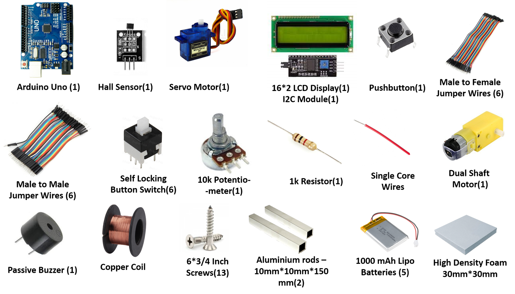
Step 2: Project General Outline

The whole setup is attached to a high-density foam piece using screws. A wooden piece or any other more rigid material would have been a better choice for this since the screws seem to lose their grip eventually because of the not-so-rigid nature of the foam.
Step 3: Connecting the Hall Sensor

I have used a hall sensor module to count the number of windings. The hall sensor is a device that is designed to detect the hall effect. There are two different types of hall sensors - analogue and digital. I have used the latter.
To know more about hall effect and how the hall sensor works, refer to this video -
Each time the magnet attached to the motor goes past the hall sensor, it goes HIGH. An interrupt function is used to count the number of times the hall sensor goes HIGH (thus counting the number of windings). The image shows how the hall sensor is connected to that Arduino.
Step 4: Connecting the LCD

The LCD display is coupled with the I2C module and connected to the Arduino. The image shows how the LCD display is connected to the Arduino.
Refer to these videos to know more about LCDs and how to connect them to the Arduino.
Step 5: Connecting the Servo Motor

The servo motor distributes the copper coil evenly across the 3D printed part. The image shows how the servo motor is connected to the Arduino.
Refer to these videos to know more about servo motors and how to work with them.
Step 6: Connecting the Push Button

The pushbutton is used to confirm the input given through the potentiometer. The image shows how the pushbutton is connected to the Arduino through a pull-up resistor.
Refer to this video to know more about pushbuttons and pull-up/pull-down resistors.
Step 7: Connecting the Buzzer

The buzzer gives a beep sound as soon as the winding is done. There are two different types of buzzers, active and passive buzzers. I have used a passive buzzer. The image shows how the buzzer is connected to the Arduino.
Refer to these videos to understand more about buzzers and how to program them.
https://www.youtube.com/watch?v=dHYKRrlPNzM&list=PLGs0VKk2DiYw-L-RibttcvK-WBZm8WLEP&index=24
Step 8: Connecting the Potentiometer

The potentiometer knob is used to give the input regarding the amount of coil to be wound around the 3D printed part. I have used a 10KOhm potentiometer. You can use a different potentiometer. Use the schematics to connect the potentiometer to the Arduino.
Refer to this video to learn more about potentiometers:
Step 9: Connecting the Motor, Battery and Self-locking Switch

Use the schematics to connect the motor to the battery through the switch. Make sure to get the exact same switch. If you don't find it, you can always get a different switch and use the continuity testing feature of the multimeter to figure out how to connect it, to perform the same action.
Step 10: Connecting the Arduino

Use the schematics to connect the Arduino to the battery. I have used a battery pack made of three Lipo cells. The total voltage of the battery pack is 11.1V (3.7V x 3). The Vin pin allows an input between 7-12V. You can use a 9V battery, commonly available at stores.
Step 11: Code
Attachments

Step 12: Calculations
NOTE: You will not need this calculation if you want to wind based on the number of windings, instead of the weight of the copper coil to be wound.
The inputs given through the potentiometer knob are just numbers between 0 -1024 (the analogue values that the Arduino reads). These values are then mapped between 0-30 (using the map function in the code). These values are nothing but the amount of copper coil (in weight) that the user wants the coil winder to wind around the 3D printed part.
The Arduino however is not equipped or assisted by sensors that can sense the weight. However, the program contains a hardware interrupt function triggered by a hall sensor, that helps the Arduino count the number of windings. Thus to relate the user's input and what the Arduino is capable of doing, a calculation outside the program has been done. It is a simple calculation that determines the number of windings required to wind a particular amount (in grams) of copper coil. The calculation equates the potentiometer input to the number of windings required to satisfy the input.
This is how it was done.
Step 1: I weighed the empty 3D printed part. Its weight was, say, 11 grams.
Step 2: Then I manually wound copper coil around it until the weight increased by 1 gram (from 11 grams to 12 grams).
Step 3: I counted the number of times I had wound. It was, say, 14 times.
Step 4: Now,
14 windings = 1 gram
Step 5: That's it. Just multiply the input from the potentiometer knob (after mapping it) by 14 to get the value of totalWindings. So, for example, if 5 grams of the copper coil has to be wound, then the value of totalWindings would be 5*14 = 70.
NOTE: Even though a significant part of the calculation involves the things that are specific for my project, the method, however, can be used for different projects.
Step 13: 3D Parts

Use the image map as reference to identify parts.
NOTES:
1. The 3D printer I used sometimes prints incorrectly. So, I had to round off a lot of the dimensions. So some of the slots/holes ended up becoming slightly bigger. Please edit the files as per your requirement. The designs are simple.
2. The lids of the "Arduino shell" and "box cover" were screwed on top. The "extension" parts were just glued using a glue gun. Frankly speaking, the "extension" parts were made because of the initial confusions in the design. However, having the "extension" parts gave me the freedom to debug the circuit while testing, without unscrewing the lids. I could just remove the extension parts along with the lid (since its just glue stick, it came off easily). You can omit the extensions by re-designing the "Arduino Shell" and "box cover" parts taller if needed.
3. If you don't find the exact screws, you can use different screws and re-design the slots/holes accordingly.
Attachments
 potentiometer knob.SLDPRT
- reset new.SLDPRT
- servo arm.SLDPRT
- stand.SLDPRT
- switch case.SLDPRT
- switch modified.SLDPRT
- arduino cover.SLDPRT
- arduino extension.SLDPRT
- arduino shell.SLDPRT
- axle new.SLDPRT
- box cover.SLDPRT
- box extension.SLDPRT
- box shell.SLDPRT
- magnet holder.SLDPRT
- motor holder.SLDPRT
- ok button.SLDPRT
- potentiometer bottom part.SLDPRT
- potentiometer botton part.SLDPRT
- servomotor case.SLDPRT


Step 14: Working Video
This is the working video
Step 15: Working
This is the downloadable file of the working video.


