

Introduction: Computer Controlled Power Switch


Want to toggle a power outlet between on or off with your computer? How about doing it with a remote? Sounds nice - I know. But the best is that you can make it all, and this will tell you how...
"Why would I want to turn a power outlet on or even OFF with my computer...?"
Ever stub your toe getting out of bed to pee in the wee (tehe) hours of the morning? Enjoy mood lighting? Hell, maybe you just want to be a dweeb like me? This will make your life a little more easy, and if it doesn't do that it'll still make you super-swanky.
The great thing about this project is that it's not limited to a light - this is a computer controlled POWER OUTLET. So long as you're using a simple house-hold appliance this project is for you.
What makes this even cooler is that you can control 8 things with your parallel port (there are 8 data pins). So if turning a light on and off isn't enough for you then you can, potentially, turn your room into a TECHNO DANCE BAR!... or not.
Warning!!!
You have to understand, before you try any of this, that I'm not responsible if you get injured; if any of your property is damaged, or if you get shocked - lighting your clothes on fire and turning you into a screaming human candle - I'm not responsible. So, please, be careful and pay close attention to any details... it'll save you a lot of annoyance and tribulation.
Mistakes only happen because of the unknown or overlooked... the closer you pay attention to what you're doing the less likely you'll be to make a stupid mistake. I know this because I am the master of stupid mistakes.
You're going to need a few things...
Step 1: Relay...


This is the heart of the beast - the actual hardware to control the outlet.
My version is in a nice little case that I scrounged from my father's junk pile... I've got a kitty cat, and I think 120V 50AMP adds up to just a little over 9 cat lifes, so it's better safe than sorry with this thing.
The main part is a special "relay". You can pick these up on ebay for pretty cheap - you could try your local electronics store, but I honestly doubt you'll have much luck. None the less - you'll need it.
So, let's do an inventory of what you'll need for this part:
- Tools
- Utility Knife
- Soldering Iron
- Solder
- Electrical Insulating Tape
- Items
- Opto Relay Model # (480D10-12)
- Extension Cord, 4ft(You'll be cutting this, so it shouldn't be your dad's/friend's/neighbour's or something)
- Safe (non-conductive) housing for the relay
- Parallel Port cable'
Ok, that's pretty much it. You can see I used some fancy eye-couplings for mine (or whatever they're called)... that's where the soldering iron comes in handy - but you'll also need it to re-attach one of the power lines on the extension cord when you cut it.
1. Simply take your extension cord and cut it - keep in mind when you're doing this that where you cut is where the relay will be placed and housed. So if you need some distance to get to the outlet, cut it towards the other end. I didn't consider that when I made mine, but I got lucky.
Now, figure out which line of the two cables you cut is the lead(positive) and which is the negative. The relay is marked which connects to which, but if you don't know anything about power outlets or extension cords this may be tricky. Good luck! :P
2. Take your eye-couplings and soldering them to the ends of the wire and crimp them so they don't come lose. Don't solder up the other wire (in my photo you can see it has black tape on it for safety) - you'll need to keep those unjoined if you want to put it in a case.
3. You'll want to refer to a guide about your parallel cable, or just test it with a current tester (to determine which pin is 1). Here's a link to the wikipedia entry on parallel ports.
This is really important - all of the software I've made is configured to run on pin 1. I should mention, again, that there are 8 pins on the parallel port to control a relay with... that means 8 unique items to control... if you don't mind buying 8 relays :P
4. So you've got your hardware done and you need to test it, right? Ok - that's good. I got to that point to, I used this great program. The webpage is in German, so uhh... here's the direct link for download.
Once you've determined that you've got a good connection and it's turning your appliance on/off you'll want to head down to the last step to check out the software I had made to control this. If you're having trouble following these steps at this point, please - PLEASE leave a comment.
If you're ready to kick this instructable into TURBO CHARGE then head on to the next step.
I love improvement, and I'm a fan of criticism. So I'll update the instructable as I get suggestions or complaints. If you notice I did anything dangerous or stupid, don't hesitate to mention it - you could be saving someone a lot of trouble.
Here's a video I made a few months ago when I was still "debugging" the relay. Hopefully it will give you some insight into the simplicity of this project, or any questions you have.
Step 2: Over Drive!

So you're ready to turn this instructable up a notch, eh? In that case, you're on the best step. This will turn your project into a swank mobile. You'll go from a slouching geek in a computer chair shouting in elation, "LOOK WHAT I CAN DO!" to Neo, from The Matrix.
I pinky promise.
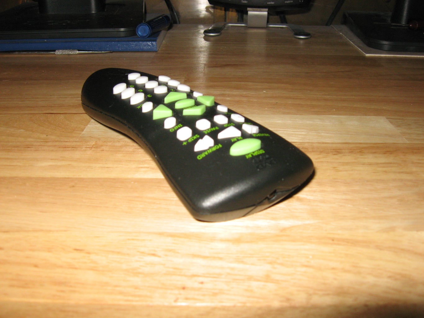
Start out by picking up a Xbox Media Remote - I don't mean the Xbox360, I mean that big black box which, if ever pressed, could be used to save your life - maybe even take a bullet.
Once you get your remote (I got mine for $14CAD from a pawn shop) you'll need to do an inventory check again - for this mod we'll need the following:
- Tools
- Soldering Iron
- Solder
- Insulating Electrical Tape
- Items
- Xbox Remote Recieving Unit
- USB cable (once again, this will be cut... so make sure you're OKAY with that.)
1. Start by popping the back off of the reciever - you'll be using your knife for this. This is really difficult, so take your time and try not to cut yourself. Remember, the more careful you are the less you'll dent and cut the reciever - which is a better looking final result.
I can't stress how hard this was for me, but I took my time and I only have a single, small, dent in the side of my reciever.
2. Once you get the cover off of the reciever you'll see some chips and stuff. Hopefully you were careful - otherwise yours may not exactly be in pristine condition...
On the reciever you'll see pins, below a chip, for the plug, which is on the other side. Going from left to right, they are as follows:
0. Ground
0. Red
0. White
0. Green
0. Yellow
0. Black
0. Ground
They're not actually colored or labled - that's the wires from your USB cable which will be attaching there.
3. You'll notice there's no yellow on your USB cable, that's because it's a strange creation of Microsoft. Don't worry, just continue carefully soldering your wires.
Once they're all attached and you're ready to test it, head down to RedCl0ud's webpage and pick up his drivers. There's also the original guide there as well, which may be more useful than mine.
I pinky promise.
Start out by picking up a Xbox Media Remote - I don't mean the Xbox360, I mean that big black box which, if ever pressed, could be used to save your life - maybe even take a bullet.
Once you get your remote (I got mine for $14CAD from a pawn shop) you'll need to do an inventory check again - for this mod we'll need the following:
- Tools
- Soldering Iron
- Solder
- Insulating Electrical Tape
- Items
- Xbox Remote Recieving Unit
- USB cable (once again, this will be cut... so make sure you're OKAY with that.)
1. Start by popping the back off of the reciever - you'll be using your knife for this. This is really difficult, so take your time and try not to cut yourself. Remember, the more careful you are the less you'll dent and cut the reciever - which is a better looking final result.
I can't stress how hard this was for me, but I took my time and I only have a single, small, dent in the side of my reciever.
2. Once you get the cover off of the reciever you'll see some chips and stuff. Hopefully you were careful - otherwise yours may not exactly be in pristine condition...
On the reciever you'll see pins, below a chip, for the plug, which is on the other side. Going from left to right, they are as follows:
0. Ground
0. Red
0. White
0. Green
0. Yellow
0. Black
0. Ground
They're not actually colored or labled - that's the wires from your USB cable which will be attaching there.
3. You'll notice there's no yellow on your USB cable, that's because it's a strange creation of Microsoft. Don't worry, just continue carefully soldering your wires.
Once they're all attached and you're ready to test it, head down to RedCl0ud's webpage and pick up his drivers. There's also the original guide there as well, which may be more useful than mine.
Step 3: Wrap Up

Hopefully you've got all the information you need to complete this project... however, if you don't - I'll give you the information I had when I made all of my parts.
I really welcome comments and criticism, so please don't hesistate to speak your mind.
Before I go and wrap this up, I have a little beef I want to clear up - if you're not interested, just skip past the italic text...
When I realized I needed custom control software for this project I did what only seemed rational, I logged on the mIRC channel #C on irc.freenode.net. All I met there was pretentious jerks who just wanted to stroke their own egos. It was horrible - I'm not exaggerating. The only favor they did me was mentioning Rent-A-Coder, and even that was done snidely.
Rent-A-Coder is a great utility for people who want to make projects, or want to concentrate on something other than programming - it's difficult enough without that insanity. It was really easy to use, and I definitely give kudos to the designer of it. Didn't cost me much, either!
So, to wrap it up - here's the software and external links I promised.
Parallel Relay Control (Command line based) Big thanks to Agustin Derregibus, my very cooperative programmer. Source included!
Parallel Relay Controller (Uses hotkey "numpad 9" to toggle pin 1 on the parallel port on/off) Included is the source, icon, and original PNG (which I made). Big thanks to my buddy Jake Kramer who made this on short notice for me!
Relais Timer (German, scroll to the bottom for the download link) (for debugging your paralell port relay, if you need it)
Original (This is the instructable that inspired my project)
RedCl0ud's Place (Has all the drivers and information you need to make the remote)
Hope you enjoyed! This is my FIRST instructable!
If you'd like to see more photos, please visit my Flickr.
