Introduction: Computer Controlled Low Voltage Dc Xmas Lights.
WARNING: DO NOT USE OR CONNECT WALL(120 or 240 volt) POWERED LIGHTS (or anything that connects to a wall socket or the like.) WITH THIS SET UP. There are imminent Fire and death hazards if you do. ONLY USE 3 VOLT DC BATTERY POWERED LIGHTS. Use common sense and safety. I will not be responsible for any issues. Please get an expert electrical/electronics technician to help if you are not sure.
How I used a computer with a parallel port to control battery powered xmas lights.
>>> Adding opto-isolation and modified battery set up, so an updated circuit is coming soon!
Coming soon, other microcontrollers.
Step 1: What's Needed:
Parts needed
8 - Strings of battery operated lights each powered by two "C" cells. (mine were from the Dollar store for a dollar each!)
8 - 2n3904 transistors (available from better electronics stores).
1 - Db25 male crimp sub connector 276-1429 or (substitute with https://www.instructables.com/id/Mini-parallel-port-break-out-cable/ or https://www.instructables.com/id/No-solder-parallel-port-break-out/ ).
1 - Db25 cover would be nice.
wire
Low wattage solder
Electrical tape
Tools:
Low wattage soldering pen
Wire cutters
Step 2: Basic Circuit
Basic circuit.
You will want to wire all the strands the same way from pins 2 - 9 off of the parallel port. You will need to know which wire from the battery case is positive (+). Fortunately the ones I bought will allow the cases to come part and you can see which one comes from the top of the battery.
You will want to cut the wire on this side of the battery to the lights. The positive side of the battery will go to collector pin on the transistor (show as C). The emitter side of the transistor will will go to ground (shown as E). The loose end on the light string will also go to ground.
Updated circuit coming soon. (opto-isolator at this point is optional).
Step 3: Doing Some Coding.
This is not a programming tutorial, but here are some hints and references. cUsing a breakout cable is a great way to test your programming without having to have all the lighting systems used.
[code]
rem turn on pin 1 on the usual default printer port (aka lpt1 on mswindows/dos systems).
out 888, 1
rem time delay to allow led to stay lit.
for x = 1 to 1000
next x
rem turn lamp off
out 888,0
[/code]
-------------------------------------------------------------------------
Test circuit and code for turning on pins 2-9 Using the lights for fun: http://www.youtube.com/watch?v=EjZmrw9JkrM
Use qbasic or freebasic on linux or mswindows for this to work.
888 =hex 0378 for printer port 1 (LPT1: 378h, LPT2: 278h ) See manual for sure.
d0 = pin 2 -2 or 0 (2^0) = 1 2 to the zero power is always 1
d1 = pin 3 -2 or 1 (2^1) = 2 2 to the first power is alway 2
d2 = pin 4 -2 or 2 (2^2) = 4 2 squared = 4
d3 = pin 5 -2 or 3 (2^3) = 8 2 cubed = 8
d4 = pin 6 -2 or 4 (2^4) = 16 etc etc.
d5 = pin 7 -2 or 5 (2^5) = 32
d6 = pin 8 -2 or 6 (2^6) = 64
d7 = pin 9 -2 or 7 (2^7) = 128
rem turns all pins off but #3
pin_number = 3
out 888, 2^(pin_number - 2)
out 888,255 to turn all lights on
out 888,0 to turn all pins off
Turn pins 2 (2-2) and pin 5 (5-2) on exclusively would be:
(2^0) + (2^3) or (1 + 8)
out 888, 9
or
out 888, (&b00001001)
rem pin------------98765432
rem D(0-7)------76543210
rem out 888, (&b00001001) << to me the simplest, just change a zero to a 1 for that led.
--------------------1
--------------------2631
--------------------84268421
(8) (1)
Better code to not change other pins status
On
rem supply your own pin number
pin_number =
z = inp(888)
out 888, (2^(pin_number - 2)) + z
Off
rem supply your own pin number
pin_number =
z = inp(888)
out 888, z -(2^(pin_number - 2))
More info on programming and interfacing:
---------------------------------------------
Example of some pseudocode;
dim duration as double
dim tim as double
dim x as integer
tim = TIMER
duration = .1
out 888,0
for x = 1 to 20
rem 00000001
tim = TIMER
out 888,1
do
LOOP UNTIL (after a while) > duration
rem 0000011
tim = TIMER
out 888,3
do
LOOP UNTIL (after a while) > duration
rem 00000111
tim = TIMER
out 888,7
do
LOOP UNTIL (after a while) > duration
rem 00001111
tim = TIMER
out 888,15
do
LOOP UNTIL (after a while) > duration
rem 00011111
tim = TIMER
out 888,31
do
LOOP UNTIL (after a while) > duration
rem 00111111
tim = TIMER
out 888,63
do
LOOP UNTIL (after a while) > duration
rem 01111111
tim = TIMER
out 888,127
do
LOOP UNTIL (after a while) > duration
rem 11111111
tim = TIMER
out 888,255
do
LOOP UNTIL (after a while) > duration
rem ---------------------------------------------------------
rem 10000001
rem tim = TIMER
rem out 888,129
rem do
rem LOOP UNTIL (after a while) > duration
rem 11111111
tim = TIMER
out 888,255
do
LOOP UNTIL (after a while) > duration
rem 01111111
tim = TIMER
out 888,127
do
LOOP UNTIL (after a while) > duration
rem 00111111
tim = TIMER
out 888,63
do
LOOP UNTIL (after a while) > duration
rem 00011111
tim = TIMER
out 888,31
do
LOOP UNTIL (after a while) > duration
rem 00001111
tim = TIMER
out 888,15
do
LOOP UNTIL (after a while) > duration
rem 00000111
tim = TIMER
out 888,7
do
LOOP UNTIL (after a while) > duration
rem 00000011
tim = TIMER
out 888,3
do
LOOP UNTIL (after a while) > duration
rem 00000001
tim = TIMER
out 888,1
do
LOOP UNTIL (after a while) > duration
rem ---------------------------------------------------------
rem 00000000
tim = TIMER
out 888,0
do
LOOP UNTIL (after a while) > duration
next x
out 888,0
end
Step 4: Watch Them Work.
I will put up a better picture later.
Step 5: Alternative Interfacing.
Coming soon.
Step 6: Beaglebone.
Test liight an led
#turn on light
#which pin: gpioA_B = (Ax32) + B or gpio1_6 = (1x32)+6 or 38
echo 38 > /sys/class/gpio/export
echo out > /sys/class/gpio/gpio38/direction
# turn led on
echo 1 > /sys/class/gpio//gpio38/value
# turn led off
echo 0 > /sys/class/gpio//gpio38/value
# free up pin
echo 38 > /sys/class/gpio/unexport
Step 7: Arduino.
Coming soon.
/* Blink without Delay
Turns on and off a light emitting diode(LED) connected to a digital
pin, without using the delay() function. This means that other code
can run at the same time without being interrupted by the LED code.
The circuit:
* LED attached from pin 13 to ground.
* Note: on most Arduinos, there is already an LED on the board
that's attached to pin 13, so no hardware is needed for this example.
created 2005
by David A. Mellis
modified 8 Feb 2010
by Paul Stoffregen
This example code is in the public domain.
http://www.arduino.cc/en/Tutorial/BlinkWithoutDelay
*/
// constants won't change. Used here to
// set pin numbers:
const int ledPin = 13; // the number of the LED pin
// Variables will change:
int ledState = LOW; // ledState used to set the LED
long previousMillis = 0; // will store last time LED was updated
// the follow variables is a long because the time, measured in miliseconds,
// will quickly become a bigger number than can be stored in an int.
long interval = 1000; // interval at which to blink (milliseconds)
void setup() {
// set the digital pin as output:
pinMode(ledPin, OUTPUT);
}
void loop()
{
// here is where you'd put code that needs to be running all the time.
// check to see if it's time to blink the LED; that is, if the
// difference between the current time and last time you blinked
// the LED is bigger than the interval at which you want to
// blink the LED.
unsigned long currentMillis = millis();
if(currentMillis - previousMillis > interval) {
// save the last time you blinked the LED
previousMillis = currentMillis;
// if the LED is off turn it on and vice-versa:
if (ledState == LOW)
ledState = HIGH;
else
ledState = LOW;
// set the LED with the ledState of the variable:
digitalWrite(ledPin, ledState);
}
}
Step 8: Raspberry Pi
old version ----------- # Turn light on cd /sys/class/gpio # Turn on pin but defaults to low. echo 17 > export# Set port direction in this case we aredoing output. echo out > gpio17/direction # Set pin high and turn on led. echo 1 > gpio17/value #Turn light offecho 0 > gpio17/value ----------------------------------- New version: You have to use the full path with commands.# Turn light on cd /sys/class/gpio # Turn on pin but defaults to low. echo "17" > /sys/class/gpio/export# Set port direction in this case we aredoing output. echo "out" > /sys/class/gpio/gpio17/direction# Set pin high and turn on led. echo "1" > /sys/class/gpio/gpio17/value #Turn light offecho "0" > /sys/class/gpio/gpio17/value================================
Step 9: Attiny230d
	.EQU DDRB = $17		; DDRB address
	.EQU PORTB = $18	; PORTB address

	.EQU LED_X = 0		; LED_X is on PB0, pin 12 of ATtiny2313

; Pins connected to LED are outputs, DDRx=1 (set):

	SBI	DDRB, LED_X	; SBI - Set Bit in I/O Register
HOP:
	SBI	PORTB, LED_X
	CBI	PORTB, LED_X
	RJMP HOP
Step 10: Standalone Blinking Light Circuits.
Blinking led attached to coin battery.
Negative resistance blinker
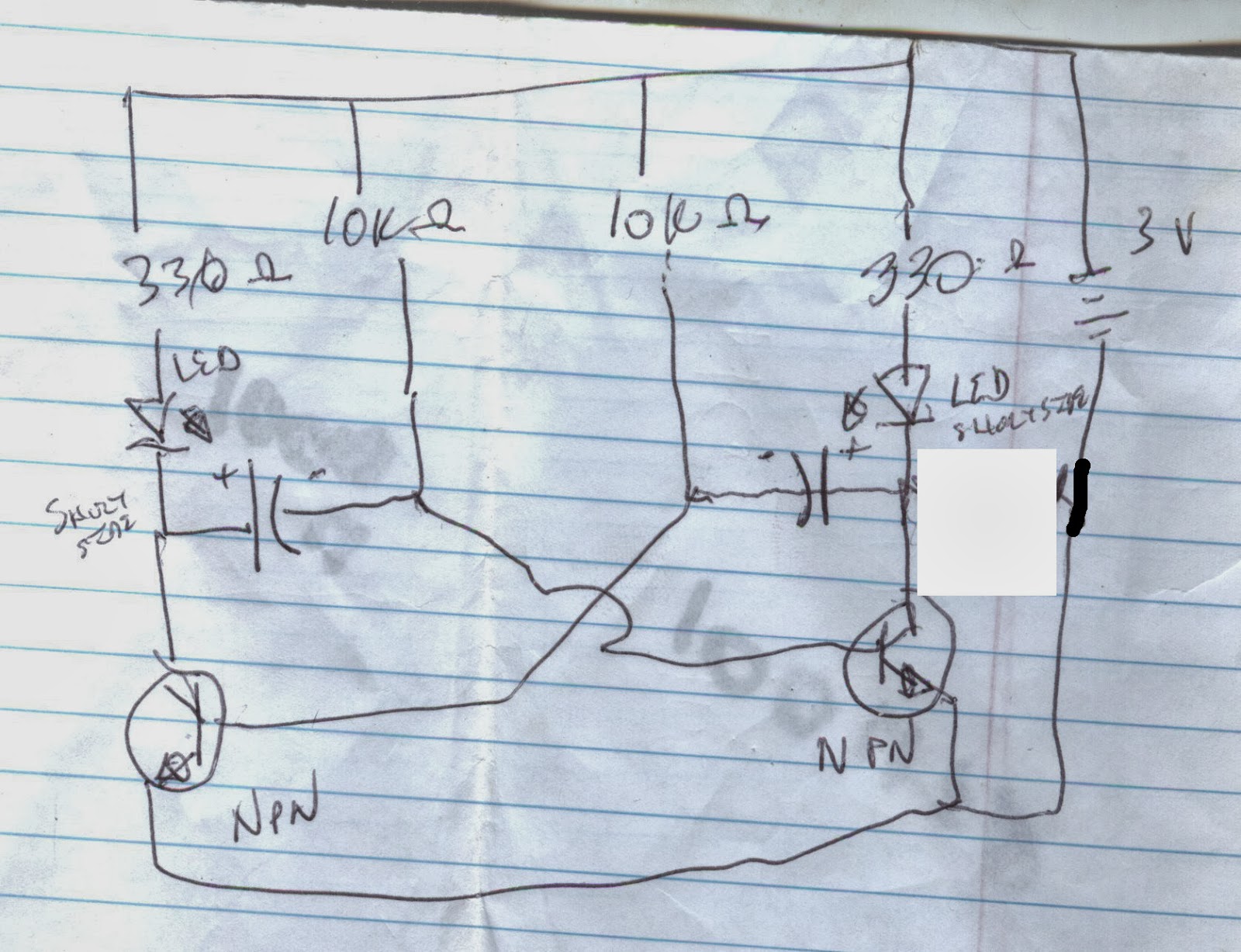
Multivibrator circuit..
Schematic:
Parts used:
2 - leds (different colors adds more mystique)
2 - 330 ohm resistors
2 - 10k ohm resistors
2 - 2n2222 transistors (npn)
2 - 100uf 50v Electrolytic capacitors
1 - 3 volt battery
Blinks fairly fast. You can exhange parts to see what it can do. The actual circuit:
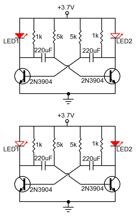
What should happen: (different circuit, but essentially the same still using npn transistors.)


