DIY Arduino RGB LED Strip IR Controller

12K1511

Intro: DIY Arduino RGB LED Strip IR Controller

Hey guys. In today’s instructable I will be showing you how you can make your own arduino based, infrared controlled, RGB LED strip controller.

The principle of the controller is quite simple. The 12v positive is connected directly to the 12v rail of the strip and the VIN pin of the arduino supplying it with power. Each mosfet source is connected to the ground of the power supply. The drain pins connect to each negative rail of the strip, for the red green and blue colors and the gate is connected through a 220ohm resistor to a PWM output pin of the arduino. When a PWM signal is sent from an arduino pin, it opens the gate of the mosfet allowing current to flow to the negative pins of the strip.


The IR receiver is connected to the 5v, ground and digital input pin of the arduino, decoding any IR signal sent in it’s direction.

STEP 1: Breadborard Testing

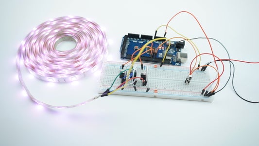
As you can see from my schematic, I used an Arduino nano as the brains of the operation, 3 Logic level mosfets as drivers for each rail of the LED Strip, a 1838 IR receiver, 3 220ohm resistors and a 12v 5A power supply.

Let’s get everything setup on a breadboard. I’m using an Arduino mega for testing which turned out to be a bad idea because, as I found out later on, some pins were not working the same on the nano as they were on the mega, but I’ll get back to that later on.

STEP 2: Arduino Code

Now let’s have a look at the arduino code.

First thing you have to do is download the latest IRRemote library from their github page. Extract the zip file and move it to your arduino libraries folder. Make sure you delete the existing RobotIRremote library from the root arduino libraries folder because it can interfere with the irremote library.

Next you can open the IRRecvDemo example sketch in your arduino IDE and change the receive pin on line 11 to 8 as that is what we are going to use on our arduino for receving the ir signal. Upload the sketch and open up the serial monitor. Now take a remote control you wish to use with your controller and press a button. If you have done everything correctly a code will show up on the serial monitor. Write down all the codes corresponding to the buttons on your remote, we are going to use them later on in our sketch.

Next, go to my github repository and download the sketch.ino file and open it up with your arduino IDE.

You can edit lines 16-39 where I defined the codes for each button on my remote, just change the HEX codes on the right side to the codes you wrote down earlier. I’m going to make a separate video and link it in the description explaining the code in detail.

A quick warning for anyone trying this project out, if you are using an arduino nano, please use exactly these pins that are setup in my sketch, some pins (5 and 11) freeze up the arduino if a pwm signal is being sent through them because the IRREMOTE library uses the built in timers of the arduino when interpreting the code and those pins need to be free. Also you can’t use the 13 pin for inputs, because it is connected to the built in LED indicator of the arduino. I have made the mistake of using those pins without properly testing first and had to order another board as a result, so please keep to these pins if you want to be safe. Upload the edited sketch to the arduino and test out all your buttons. If everything goes to plan, you should have all the buttons working correctly and displaying the colors you want. Intensity up and down buttons are used to dim the colors if you are in color mode, and speed up and slow down the animations if you are using one of the 4 animation I setup.

STEP 3: PCB Order

Now it’s time to take our project from the breadboard to an actual PCB. I used the EasyEDA online app to create the schematic and the board layout. I will show you how you can get your PCB design printed and shipped professionally by JLCPCB.

When you open the PCB design in EASYEDA, you have to click on the gerber output button in the software. Next click on Download Gerber files.

Now head on to JLCPCB.com and click on the quote now button. Upload your gerber file and you should see how your finished PCB will look like.

Below you can edit the quantity, thickness, colors etc. I went with the default settings mostly, only changed the color to blue cause I think it looks nicer. When you’re done, click on the save to cart button. After that you can go to the checkout page, enter your shipping and payment information and when your done, you can expect your PCB’s to arrive very shortly.

After about a week of waiting my PCB’s have arrived nicely and securely packaged. I must say that I’m quite happy with the overall quality. For this price it is definitely not worth trying to make your own, make sure you check our their website and you will even have free shipping on your first order if you do so.

STEP 4: PCB Assembly and Soldering

Now it’s time to assemble everything on our newly printed board. When soldering always try to solder the smallest parts first and then go on to the larger ones, makes it much easier. To connect the arduino, led strip and ir receiver i used female straight pin headers instead of soldering the components directly. That way if you accidentally fry your arduino or anything else, they can be changed easily, and you can reuse your board without any issues. The only components I soldered in directly were the mosfets and the dc power jack.

When everything is soldered in, we can connect our components. Make sure you connect the LED strip correctly, the 12v rail is the pin on the right side and the negative rails are pins 1, 2 and 3 from the left. And of course don’t put your arduino in the wrong way because you can fry it.

STEP 5: First Power on and Conclusion

When you have all the components in place, connect the 12v power supply to the board and make sure everything works.

And that’s it! Your DIY Arduino based LED strip controller is ready. I hope you will have as much fun as I did building this project. I must say that I have learned a lot and hopefully you will too. All the parts used in the project and links I mentioned are in the video description. Thank you so much for all the support to my channel, it really means a lot. If you like the video, please leave a like and subscribe for future videos because that helps me out a lot. Have fun with your LED controller and I will see you in the next one! Cheers

7 Comments

Hello my friend,
I like your project very much. I have a remote similar to the one in your project that I bought before. I have uploaded the code and there is no problem. However, I can't get PWM signal. The remote in my hand is solid. It works in NEC protocol. I get an incorrect code warning every time I press a key on the serial monitor. I'm getting same decimal numbers or FFFFFFFF code when pressing every key. Can you help me?
I had the same problem. First is the IRreceiver library is updated and no longer works with the code, second problem is when it is decoded, there are too many bytes (4) in the decoded code for the switch statements. As 2 of the bytes are always the same for these basic IR remotes (they are commented out in the code below in the #define's), the code can be truncated to remove them. Here is the modified code that works with the newer library and has the truncation from 4 byte codes to 2 byte codes:

#include
int recvPin = 8; // IR Receiver - Arduino Pin Number 8
int redPin = 10; // RED Output Pin
int greenPin = 9; // GREEN Output Pin
int bluePin = 6; // BLUE Output Pin
int intensity = 10; // Intensity variable
int speedValue = 5; // Speed Variable
int currentColors[] = {0, 0, 0}; // Current Color outputed variable (black by default)
bool customLoop = false; // Variable telling us we are in a custom animation loop
unsigned long previousMillis = 0; // variable for the delay function
//IRrecv irrecv(recvPin);
//decode_results results;
// Defining hex codes for the remote
#define ON_CODE 0xFC03//EF00
#define OFF_CODE 0xFD02//EF00
#define INTENSITY_UP_CODE 0xFF00//EF00
#define INTENSITY_DN_CODE 0xFE01//EF00
#define RED_CODE 0xFB04//EF00
#define GREEN_CODE 0xFA05//EF00
#define BLUE_CODE 0xF906//EF00
#define WHITE_CODE 0xF807//EF00
#define ORANGE_CODE 0xF708//EF00
#define TURQUOISE_CODE 0xF609//EF00
#define NAVY_CODE 0xF50A//EF00
#define BROWN_CODE 0xF30C//EF00
#define TEAL_CODE 0xF20D//EF00
#define PURPLE_DARK_CODE 0xF10E//EF00
#define ORANGE_LIGHT_CODE 0xEF10//EF00
#define BLUE_LIGHT_CODE 0xEE11//EF00
#define PINK_DARK_CODE 0xED12//EF00
#define YELLOW_CODE 0xEB14//EF00
#define BLUE_BABY_CODE 0xEA15//EF00
#define PINK_CODE 0xE916//EF00
#define FLASH_CODE 0xF40B//EF00
#define STROBE_CODE 0xF00F//EF00
#define FADE_CODE 0xEC13//EF00
#define SMOOTH_CODE 0xE817//EF00
// defining the available colors one by one
int BLACK_COLOR[3] = {0, 0, 0};
int RED_COLOR[3] = {255, 0, 0};
int GREEN_COLOR[3] = {0, 255, 0};
int BLUE_COLOR[3] = {0, 0, 255};
int WHITE_COLOR[3] = {255, 255, 255};
int ORANGE_COLOR[3] = {255, 128, 0};
int TURQUOISE_COLOR[3] = {0, 255, 128};
int NAVY_COLOR[3] = {0, 76, 153};
int BROWN_COLOR[3] = {153, 76, 0};
int TEAL_COLOR[3] = {0, 102, 102};
int PURPLE_DARK_COLOR[3] = {102, 0, 51};
int ORANGE_LIGHT_COLOR[3] = {255, 153, 51};
int BLUE_LIGHT_COLOR[3] = {0, 255, 255};
int PINK_DARK_COLOR[3] = {255, 0, 128};
int YELLOW_COLOR[3] = {255, 255, 0};
int BLUE_BABY_COLOR[3] = {51, 153, 255};
int PINK_COLOR[3] = {255, 102, 178};
int code = 0;
// defining all the available remote codes in an array
int AVAILABLE_CODES[24] = {ON_CODE, OFF_CODE, INTENSITY_UP_CODE, INTENSITY_DN_CODE, RED_CODE, GREEN_CODE, BLUE_CODE, WHITE_CODE, ORANGE_CODE, TURQUOISE_CODE, NAVY_CODE, BROWN_CODE, TEAL_CODE, PURPLE_DARK_CODE, ORANGE_LIGHT_CODE, BLUE_LIGHT_CODE, PINK_DARK_CODE, YELLOW_CODE, BLUE_BABY_CODE, PINK_CODE, FLASH_CODE, FADE_CODE, SMOOTH_CODE, STROBE_CODE};
// defining all the available colors in an array
int AVAILABLE_COLORS[16][3] = {{255, 0, 0}, {0, 255, 0}, {0, 0, 255}, {255, 255, 255}, {255, 128, 0}, {0, 255, 128}, {0, 76, 153}, {153, 76, 0}, {0, 102, 102}, {102, 0, 51}, {255, 153, 51}, {0, 255, 255}, {255, 0, 127}, {255, 255, 0}, {51, 153, 255}, {255, 102, 158}} ;
void setup() {
Serial.begin(115200);
IrReceiver.begin(recvPin, ENABLE_LED_FEEDBACK); // Start the receiver
pinMode(redPin, OUTPUT);
pinMode(greenPin, OUTPUT);
pinMode(bluePin, OUTPUT);
}
// function for interpreting the incoming code and eighter setting a fixed color or starting a custom loop function
void interpretRemoteCode(int code) {
int randomColor[3] = {random(256), random(256), random(256)};
switch (code) {
case ON_CODE: setColor(randomColor); break;
case OFF_CODE: setColor(BLACK_COLOR); break;
case INTENSITY_UP_CODE: raiseIntensity(); break;
case INTENSITY_DN_CODE: lowerIntensity(); break;
case RED_CODE: setColor(RED_COLOR); break;
case GREEN_CODE: setColor(GREEN_COLOR); break;
case BLUE_CODE: setColor(BLUE_COLOR); break;
case WHITE_CODE: setColor(WHITE_COLOR); break;
case ORANGE_CODE: setColor(ORANGE_COLOR); break;
case TURQUOISE_CODE: setColor(TURQUOISE_COLOR); break;
case NAVY_CODE: setColor(NAVY_COLOR); break;
case BROWN_CODE: setColor(BROWN_COLOR); break;
case TEAL_CODE: setColor(TEAL_COLOR); break;
case PURPLE_DARK_CODE: setColor(PURPLE_DARK_COLOR); break;
case ORANGE_LIGHT_CODE: setColor(ORANGE_LIGHT_COLOR); break;
case BLUE_LIGHT_CODE: setColor(BLUE_LIGHT_COLOR); break;
case PINK_DARK_CODE: setColor(PINK_DARK_COLOR); break;
case YELLOW_CODE: setColor(YELLOW_COLOR); break;
case BLUE_BABY_CODE: setColor(BLUE_BABY_COLOR); break;
case PINK_CODE: setColor(PINK_COLOR); break;
case FLASH_CODE: flash(); break;
case STROBE_CODE: strobe(); break;
case FADE_CODE: fade(); break;
case SMOOTH_CODE: crossFade(); break;
}
}
// raise the intensity of light or the speed of animation
void raiseIntensity() {
if (!customLoop) {
if (intensity <= 9) {
intensity++;
}
} else if (speedValue <= 9) {
speedValue++;
}
}
// lower the intensity of light or the speed of animation
void lowerIntensity() {
if (!customLoop) {
if (intensity >= 2) {
intensity--;
}
} else if (speedValue >= 2) {
speedValue--;
}
}
// helper function to check if a value is present in an array
int existsInArray(int compareValue, int arrayName[], int arraySize) {
for (int x = 0; x < arraySize; x = x + 1) {
if (arrayName[x] == compareValue) {
return true;
}
}
return false;
}
// set the currentColors variable
void setColor(int colors[]) {
currentColors[0] = colors[0];
currentColors[1] = colors[1];
currentColors[2] = colors[2];
}
// calculate the intensity and send the current color out via the output pins
void sendColor()
{
if (customLoop == false) {
int red = currentColors[0];
int green = currentColors[1];
int blue = currentColors[2];
int mappedIntensity = map(intensity, 0, 10, 0, 255);
int redComputed = map(red, 0, 255, 0, mappedIntensity);
int blueComputed = map(blue, 0, 255, 0, mappedIntensity);
int greenComputed = map(green, 0, 255, 0, mappedIntensity);
analogWrite(redPin, redComputed); // Sends PWM signal to the Red pin
analogWrite(greenPin, greenComputed);
analogWrite(bluePin, blueComputed);
}
}
// check for a code from the remote every 100 milliseconds
void loop() {
unsigned long currentMillis = millis();
if (currentMillis - previousMillis >= 100) {
previousMillis = currentMillis;
findCode();
}
}
// decode remote control code and if found in the array of available codes interpret it
void findCode() {
if (IrReceiver.decode()) {
code = IrReceiver.decodedIRData.decodedRawData>>16;
if (existsInArray(code, AVAILABLE_CODES, 24)) {
Serial.println("Code Found");
interpretRemoteCode(code);
if (code != FLASH_CODE && code != STROBE_CODE && code != FADE_CODE && code != SMOOTH_CODE) {
customLoop = false;
sendColor();
}
} else {
Serial.println("Invalid Code");
Serial.println(code, HEX);
}
IrReceiver.resume();
}
}
// custom flashing function
void flash() {
customLoop = true; // set the variable so that the program knows we are in a custom animation loop
unsigned long previousMillis = 0;
while (customLoop) { // while we are still in the custom animation loop
if (IrReceiver.decode()) { // check for incomming ir code and if found exit the loop and interpret the code
code = IrReceiver.decodedIRData.decodedRawData>>16;
if (existsInArray(code, AVAILABLE_CODES, 24) && code != INTENSITY_UP_CODE && code != INTENSITY_DN_CODE && code != FLASH_CODE) {
Serial.println("return break");
return; break;
interpretRemoteCode(code);
} else if (code == INTENSITY_UP_CODE) { // if the code is to raise or lower the speed
raiseIntensity(); // raise the speed
} else if (code == INTENSITY_DN_CODE) {
lowerIntensity(); // or lower the speed
}
IrReceiver.resume();
}
int randomNumber = random(16); // get a random number from 0 to 16
// set temporary variales for the red, green and blue values
int red = AVAILABLE_COLORS[randomNumber][0];
int green = AVAILABLE_COLORS[randomNumber][1];
int blue = AVAILABLE_COLORS[randomNumber][2];
unsigned long currentMillis = millis();
// set a X animation delay from 200 to 3000 milliseconds based on the speed variable
int mappedSpeed = map(speedValue, 10, 1, 200, 3000);
// every X milliseconds
if (currentMillis - previousMillis >= mappedSpeed) {
previousMillis = currentMillis;
// send the color variables through the digital ouput pins
analogWrite(redPin, red);
analogWrite(greenPin, green);
analogWrite(bluePin, blue);
}
}
}
void strobe() {
customLoop = true;
unsigned long previousMillis = 0;
int i = 1;
while (customLoop) {
if (IrReceiver.decode()) {
code = IrReceiver.decodedIRData.decodedRawData>>16;
if (existsInArray(code, AVAILABLE_CODES, 24) && code != INTENSITY_UP_CODE && code != INTENSITY_DN_CODE && code != STROBE_CODE) {
Serial.println("return break");
return; break;
interpretRemoteCode(code);
} else if (code == INTENSITY_UP_CODE) {
raiseIntensity();
} else if (code == INTENSITY_DN_CODE) {
lowerIntensity();
}
IrReceiver.resume();
}
int randomNumber = random(16);
int red = AVAILABLE_COLORS[randomNumber][0];
int green = AVAILABLE_COLORS[randomNumber][1];
int blue = AVAILABLE_COLORS[randomNumber][2];
unsigned long currentMillis = millis();
int mappedSpeed = map(speedValue, 10, 1, 50, 1500);
if (currentMillis - previousMillis >= mappedSpeed) {
previousMillis = currentMillis;
if ( (i % 2) == 0) {
analogWrite(redPin, red); // Sends PWM signal to the Red pin
analogWrite(greenPin, green);
analogWrite(bluePin, blue);
} else {
analogWrite(redPin, 0); // Sends PWM signal to the Red pin
analogWrite(greenPin, 0);
analogWrite(bluePin, 0);
}
i++;
}
}
}
void fade() {
customLoop = true;
unsigned long previousMillis = 0;
int i = 1;
int randomNumber = random(16);
int red = AVAILABLE_COLORS[randomNumber][0];
int green = AVAILABLE_COLORS[randomNumber][1];
int blue = AVAILABLE_COLORS[randomNumber][2];
Serial.println("final colors");
Serial.println(red);
Serial.println(green);
Serial.println(blue);
Serial.println("-----------");
while (i < 255) {
if (IrReceiver.decode()) {
code = IrReceiver.decodedIRData.decodedRawData>>16;
if (existsInArray(code, AVAILABLE_CODES, 24) && code != INTENSITY_UP_CODE && code != INTENSITY_DN_CODE && code != FADE_CODE) {
Serial.println("return break");
return; break;
interpretRemoteCode(code);
} else if (code == INTENSITY_UP_CODE) {
raiseIntensity();
} else if (code == INTENSITY_DN_CODE) {
lowerIntensity();
}
IrReceiver.resume();
}
unsigned long currentMillis = millis();
int mappedSpeed = map(speedValue, 10, 1, 10, 100);
if (currentMillis - previousMillis >= mappedSpeed) {
previousMillis = currentMillis;
int mappedRedIntensity = map(i, 0, 255, 0, red);
int mappedRed = red != 0 ? map(red, 0, red, 0, mappedRedIntensity) : 0;
int mappedGreenIntensity = map(i, 0, 255, 0, green);
int mappedGreen = green != 0 ? map(green, 0, green, 0, mappedGreenIntensity) : 0;
int mappedBlueIntensity = map(i, 0, 255, 0, blue);
int mappedBlue = blue != 0 ? map(blue, 0, blue, 0, mappedBlueIntensity) : 0;
analogWrite(redPin, mappedRed);
analogWrite(greenPin, mappedGreen);
analogWrite(bluePin, mappedBlue);
i++;
}
}
while (i > 0) {
if (IrReceiver.decode()) {
code = IrReceiver.decodedIRData.decodedRawData>>16;
if (existsInArray(code, AVAILABLE_CODES, 24) && code != INTENSITY_UP_CODE && code != INTENSITY_DN_CODE && code != FADE_CODE) {
Serial.println("return break");
return; break;
interpretRemoteCode(code);
} else if (code == INTENSITY_UP_CODE) {
raiseIntensity();
} else if (code == INTENSITY_DN_CODE) {
lowerIntensity();
}
IrReceiver.resume();
}
unsigned long currentMillis = millis();
int mappedSpeed = map(speedValue, 10, 1, 10, 100);
if (currentMillis - previousMillis >= mappedSpeed) {
previousMillis = currentMillis;
int mappedRedIntensity = map(i, 0, 255, 0, red);
int mappedRed = red != 0 ? map(red, 0, red, 0, mappedRedIntensity) : 0;
int mappedGreenIntensity = map(i, 0, 255, 0, green);
int mappedGreen = green != 0 ? map(green, 0, green, 0, mappedGreenIntensity) : 0;
int mappedBlueIntensity = map(i, 0, 255, 0, blue);
int mappedBlue = blue != 0 ? map(blue, 0, blue, 0, mappedBlueIntensity) : 0;
analogWrite(redPin, mappedRed);
analogWrite(greenPin, mappedGreen);
analogWrite(bluePin, mappedBlue);
i--;
if (i == 0) {
fade();
}
}
}
}
int redVal = 0;
int grnVal = 0;
int bluVal = 0;
int prevR = redVal;
int prevG = grnVal;
int prevB = bluVal;
int calculateStep(int prevValue, int endValue) {
int step = endValue - prevValue; // What's the overall gap?
if (step) { // If its non-zero,
step = 256 / step; // divide by 1020
}
return step;
}
int calculateVal(int step, int val, int i) {
if ((step) && i % step == 0) { // If step is non-zero and its time to change a value,
if (step > 0) { // increment the value if step is positive...
val += 1;
}
else if (step < 0) { // ...or decrement it if step is negative
val -= 1;
}
}
// Defensive driving: make sure val stays in the range 0-255
if (val > 255) {
val = 255;
}
else if (val < 0) {
val = 0;
}
return val;
}
void crossFade() {
int randomNumber = random(16);
customLoop = true;
unsigned long previousMillis = 0;
// Convert to 0-255
int R = AVAILABLE_COLORS[randomNumber][0];
int G = AVAILABLE_COLORS[randomNumber][1];
int B = AVAILABLE_COLORS[randomNumber][2];
int stepR = calculateStep(prevR, R);
int stepG = calculateStep(prevG, G);
int stepB = calculateStep(prevB, B);
int i = 0;
while (i <= 256) {
if (IrReceiver.decode()) {
code = IrReceiver.decodedIRData.decodedRawData>>16;
if (existsInArray(code, AVAILABLE_CODES, 24) && code != INTENSITY_UP_CODE && code != INTENSITY_DN_CODE && code != SMOOTH_CODE) {
Serial.println("return break");
return; break;
interpretRemoteCode(code);
} else if (code == INTENSITY_UP_CODE) {
raiseIntensity();
} else if (code == INTENSITY_DN_CODE) {
lowerIntensity();
}
IrReceiver.resume();
}
unsigned long currentMillis = millis();
int mappedSpeed = map(speedValue, 10, 1, 50, 150);
if (currentMillis - previousMillis >= mappedSpeed) {
previousMillis = currentMillis;
redVal = calculateVal(stepR, redVal, i);
grnVal = calculateVal(stepG, grnVal, i);
bluVal = calculateVal(stepB, bluVal, i);
analogWrite(redPin, redVal); // Write current values to LED pins
analogWrite(greenPin, grnVal);
analogWrite(bluePin, bluVal);
i++;
if (i == 257) {
prevR = redVal;
prevG = grnVal;
prevB = bluVal;
crossFade();
}
}
}
}
I have two questions:
1. Can you explain (or give me a link/info source) why you need a resistor between the arduino output pin and the gate of the mosfets?
2. Why is the resistor value chosen to be 220ohm? Why not less or more?
These questions are solely to increase my understanding of electronics ^-^
Basicly you need resistor between cause transistor/mosfet will draw more current than arduino can handle and you will eventualy fry arduino. 220 ohm is some basic resistor for arduno, its simply calculatef by ohms law (I = U/R); u is voltage = 5V, R is ressistance of ressistor, I is current. (Arduno can supply max 20mA of current). Hope this helps ;)
Well I had the same question at first. Then I removed the resistors and connected it directly with a wire instead. But then I noticed that my Arduino atmega328p chip is heating up very quickly and I couldn't even touch it with my finger. Because of that, I was dangerously close frying up my Arduino. I replaced the wires with the resistors again. I used 100 ohm resistors, and mine works very well, it wont heat up anymore
Can i replace other mosfet? If i can replace, please tell me the name of mosfet. Thank You. (my english skill is not good)

Great first Instructable. You should think about entering this into the First Time Authors contest.