

Introduction: Automated DWC Hydroponic System

This instructable’s aim is to teach people how to create a watering system from scratch.
This is done by controlling the various factors that affect a plant’s growth through the use of a sensor and a smart mini-controller – such as Arduino Uno. By the end of this paper, you will be able to create a fully functional watering system for your plant. In my specific instance, I have chosen to focus on a Hydroponic kind of watering, more specifically a Deep Water Culture Hydroponic System. This soil-less hydroponic system can be created from ordinary elements, such as a bucket, plastic tubes, and water.
The system will be automated and ran by an Arduino board. Being an easily constructible and cheap system to build, it is utilised by both home hydroponic growers, and commercial growers.
Although the founding concept of the system is simple, there is a variety of imaginative ways to build and use water culture systems built out of different materials.
Whilst there are plenty of tutorials online on how to make a DWC from scratch, none of these explore how to link the DWC to an Arduino, so to make it more self-efficient. Whilst the project hereby presented is more strongly concerned with the system of automation through the use of Arduino, I intend to implement an IOT system in an improved future release of this project. Though, whilst the former project is solely ran by Arduino, controlled by two buttons and a LCD screen, withholds no data log and temperature and humidity can be displayed on the screen, the latter future one will reach a whole different level.
In fact, this will be ran by a Rasberrypy alongside the Arduino, where everything will be displayed on a five inches touch screen that will record the data, send it to the user via message and have pre-scheduled plans for a variety of different seeds.
Step 1: Arduino Sensors
As the Arduino Project has such a great background community, a
variety of modules can be bought with the board itself.
Each module can either have an analogical or a digital reading of a value (e.g. temperature, humidity etc). All modules are easy to wire and most of them come with an additional library that can be used to make the reading easy and straightforward, when it comes to the coding side of the system.
The modules can either return a digital or an analogical signal, hereby interpreted by the Arduino through its pins. On the one hand, the digital is discrete time signals generated by digital modulation, whereas, on the other hand, the analogical signal is a continuous signal representative of physical measurements. Furthermore, a couple of low voltage pumps will be used to stir both air and water, alongside the use of the sensor.
Step 2: List of Components
•Plastic Bucket (50 lt)
•Plastic tubes (buyable in any gardening shop)
•Net pots (this pots are specific to the DWC system)
•x2 Water pump (12V)
•Fertilizers container (5 lt)
•Humidity and temperature sensor
•Water level sensor
•Air pump (6V, find those in aquarium stores)
•Aquarium air stone
•Relay switch
•Several Resistors
•Wires
•Arduino board
•Real Time Clock module (DS3231)
•LCD module
•Push button x2
Step 3: About Components

All the listed components have been choosen for a reason:
Arduino board: The brand does not matter when it comes to the Arduino Board (if it's a clone or not). The Uno board is probably the one suiting this DIY experiment better, as it does not have many pins, and the experiment itself does not require any Arduino shield or additional components.
Relay switch:This has been a long time coming find. As my knowledge in the electronic fields is scarce, it took me a while to figure which switch would be best to use, mainly due to the different voltages of each component. As the Arduino alone can only provide 5V of energy, two additional power sources had to be attached to it (9V batteries). Though, the handling of a 12V current can become dangerous, as the component risks being fused if not wired correctly or it can harm the functionality of the board itself. The Relay switch works in a straightforward way: it has a physical switch, being able to shift between a normally open and close circuit. When the current is not needed, this gets stuck in a circuit that simply encloses the current flow between the battery(+) and the battery(-). A mosphet would have also worked fine, though I believe the Relay switch to be safer and more practical.
12V water pump: this I found on the web for a ridicoulously cheap price, it needs to be immersed in the water in order to work. Beside that, it works just as fine.
6V Air pump: i ordered this from china and it is perfect in doing what i need it to do, it pumps air and it doesnt require an high voltage or anything. It took one month to be shipped but it was definetly worth.
All the gardening elements (plastic tubes, net pots etc.) have been bought online fom a Gardening Website.
DHT22 Temperature & Humidity Sensor: This sensor is a way more accurate than the DHT11 and the adafruit library for its usage is easy and neat (Link to library page).
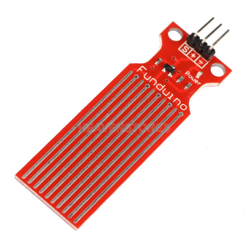
For the water level sensor I used this type though any other model will do as well. No library is needed as this module returns an analog valuewhich can be mapped accordingly to every container.
Last but not least the Real Time Clock module (DS3231), I have been looking for the correct module for a long time, then I found this instructable which is as brilliant and very easy to follow. It also linked me to this fantastic library, – all credits go to these guys who made it extremely easy to understand, where the manual isshort but very well explained.
Step 4: How to Begin…

First of all we need to make place for all the parts to be assembled:
- Cut a round hole on the bucket’s lid, where the dimension should be the same as the top part of the net pot. In my instance, I had no laser cut tool, so I just used a cutter and a compass. It is better to draw the shape with the marker attached to the compass and cut it afterward, as binding the compass leg and the cutter did not work nicely.
- Now you should have everything ready to put the DWC hydroponic system together. Connect the air lines to the air stones, and place them at the bottom of the bucket. Power the air pump, place the lid on the bucket and insert the plant basket/pot. Fill the bucket with good quality water, high enough so the bottom of the basket/pot is about 3/4 inches underwater. Take the lid back off and mark the water line inside with a permanent marker. This will be the max-level sign for the water level sensor.
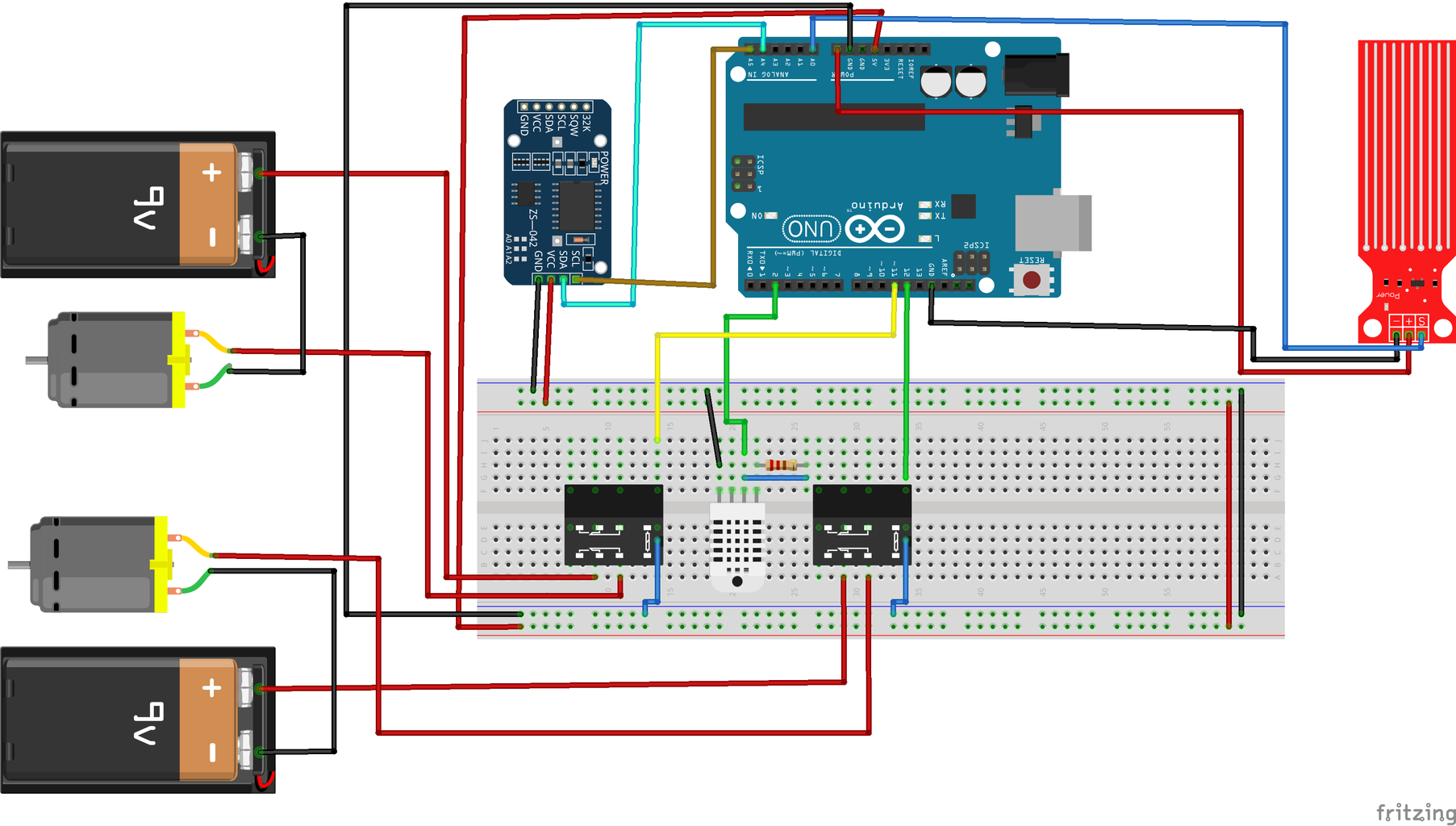
- All the wiring of the components is explained in the fritzing diagram. It is fairly easy as the coding so far is just a HIGH and LOW. To turn it on and off you can use the blink sketch. Open arduino IDE and go File> Examples > Basics> Blink. Change the variables saving the pin number, and you’re good to go.
At this point, you should have successfully completed a functional system. All the components added from now on are necessary only in terms of making the project more interactive with the user. It should more or less look like the one in the picture attached on this step. It should work just as fine, I just found it too much an effort to have nothing more than an electronic system, which you should switch on and off when you think it is the right time to do so. Implying an arduino would just make the bucket self-efficient, where water is poured when needed, the user is advised in case either the temperature or humidity are too high.
Step 5: Adding Automation
As I have previously mentioned, I will add two levels of
automation for this project. At the end of these instructables you will clearly know how to build a system that returns on a LCD screen the values needed for the growing of the plant to happen. So it will be able to:
• Communicate to the user whether everything is ok (check of temperature and humidity)
• Be automated in terms of how many times a day the plant will need watering and for how long. Though, it will still require the user’ input.
• Take care of the time of growth.
• In the occasion where the system faces some errors, it will notify the user with a red LED and, maybe, a warning message on the LCD screen.
However, in the following pages I will explain how to link the system already built to the internet, through a Raspberry PI. It will have a proper touch screen and a neat user interface. Additionally, it will notify the user through messages or emails and it will eventually know how to grow certain kinds of seeds (information database). As for the LCD screen, I have printed a 3D model found on the web and I’ll be using it to encapsulate the Arduino and the LCD in one block. Is not great but it worked fine, beside the fact I've adjusted its size with some cardboard and some foam.
Step 6: Plan and Practice

The way I've approached the final part fo the building is just trying to have an idea of where to put the compnents inside the bucket. So I've drawn the components location with a marker inside the bucket and then placed them inside and stick them with some glue and protect the wires with water proof tape.
The case with the arduino the two buttons and the LCD is going to be outside the bucket as a centralin.
The wiring is explained in the fritzing, but the Real time clock and the LCD modules are missing from the diagram, they will be explained in a step further on.
The sketch attached if uploaded to an arduino which is wired in a correct way, returns the read of temeprature and Humidity. The library makes error handling reeeaally easy.
The sketch also has a ReadWaterLevel function, which returns the analog read of the water level which can be mapped to return an error if the water is too much or too little.
Attachments

Step 7: Showcase
This is the final functional prototype.
Step 8: Add Real Time Clock


The adding of a real time clock module and making some
kind of alert, when it is needed to warn the user, is the final step of these instructables.
First, let’s take a look at the final wiring and the proto-code, then we can get them down to practice.
Wiring:
VCC -> Arduino 5V
GND -> Arduino GND
SCL -> SCL or A5
SDA -> SDA or A4
The instructables I have personally used to wire up the real time clock shows some doubts in regards of the existence of dedicated pins for SCL and SDA. I made my research, and I can claim that it is correct: Analog pin 5 and Analog pin 4 are dedicated, and are the ones I recommend to use. Additionally, the reason for the right usage of the battery slot in this particular real time clock module was not explained.
As I was researching, I found this page that explains that the batter needed is not only a Lithium 20132 battery, as it needs to be rechargeable, where the circuit of the module is designed to charge power to the battery and we DO NOT want to charge a no-rechargeable battery.
The sketch attached set the day and time for the code in the next step. We will add the user input to set the final part: current day and time, plus programming the watering.
Attachments
Step 9: Adding an LCD Screen


Afterreading some tutorials on the LCD components and its beautiful library, I have completed the wiring of a LCD correctly, and wrote a little program, which – based on the RTC module- prints day and time.
The next step is to add the user input and information log (humidity, temperature and water).
As a side note, tutorials online are good but they somehow make the whole process look more complicated than it actually is.
First of all, all we need this for is simple tasks, as it will print only some values and some text.
As shown in the image attached, the LCD pins are divided in pins going to vcc and gnd; pins going to digital read, another one to vcc for screen retro-illumination, and some final others for tasks such as writing and reading.
Step 10: Prototype
Coding:
I will try to explain you the organisation of the code’s structure. If you look at the video embedded, I tried to show the main functions our program should have (as you can see I’m no graphic designer). First of all, I want the program to check whether the user needs to initialise a watering program. The user is asked to set Day & Time and, then, decide, how often water will be needed and for how long.
The two buttons will direct all inputs. Each piece’s final wire is going to come in the next step, as for now I will limit myself to explain and protocode:
main(){
If (CheckButtonPress())
{
If only one is pressed, activate the pump and stop only at the next click.
If both are pressed à make numbers blink and let the user decide date and time, where one button is to increase and the other to complete).
}
if(CheckWaterLevel() ) {alert} //this two functions are bool and return 0 if nothing happens
if(CheckTempAndHuml() ) {alert}
if(IsTimeToWater()) {Start_pumps()}
}
Step 11: Adding User Input


I want to keep the input as simple as possible so that anyone can use it.
Two buttons: one for increasing the numbers, the other to select choices. If pressed together, the user can access the setting of time program. If nothing has been set (first use), the user is asked to set date and time. Once this is done, the screen should display date & time by default. If one button is pressed, screen should display humidity / temperature. If any value is too high, the user will be notified with a warning message.
In a first step (first video), I have worked on the input and then I have added the temperature and humidity (second video).
Attachments
Step 12: Finalising
The only missing step at this point is adding all components to the bucket. Glue/solder what needs soldering; write more codes on how many times the water of the plant is needed and for how long (plus warning messages for high and low water levels).
In the first video, I have improved the looking of the set day function and added the functionality of the water level sensor.
In the second video, I will also show how to program the water levels.
Code attached is the final one and the fritzing stays the same as the last few steps.
Final explanations regarding the code:
In the sketch attached, you will notice how I have preferred a more procedural approach to coding this program. I do find programs way easier to handle when having simple functions and while loops. For instance, every time you are setting the time, date, and program, each of these should have its own loop. This means that any other action can take place while you are setting things up. This is neat if you want to change the time closer to the previous watering time – so that it avoids the water to start while you are setting the new program.
Bools:
Bool set -> whilst this is false, the program remains in the while loop (each while loop is for only one variable, eg. Time & date). If the set button is pressed, it should set ‘set’ to true, consequently breaking out of the loop. Before the next loops, it should set it back false (and so on). At the very end, the whole function should be reset to false as it would have exited the functions being true, and messing things up in case of a re-set.
Bool Pump_ON -> this is for manual watering only. If the left button is pressed (and nor program is running – next bool-), turn the pump on until the next button is pressed.
Bool Prog_Run -> If the manual button is pressed but a watering program is running, ignore the input. To stop a running water program, the user will need to re-set the program (in case you’re no longer happy with the previous one).
Attachments
Step 13: Getting Pieces Toghether


There is not a correct way to approach the design and the final mounting of all the pieces. I decided for now to stick with the easiest design (a bucket), instead of going for a more fancy one (the IKEA one is one of my favourite).
Anyway I have used some plastic tubes and some gardening watering cans to achieve the final product. I followed this steps:
- Glue the pumps in safe places, remembering that the order matters (always check water in and out BEFORE gluing).
- Stick the modules as well and put some tape on them, at least on the part where cables get connected.
- Use a three exit piece of plastic to drive the water either to the plant or to another plastic pipe which leads to a valve, from this, in order to empty the system when it needs to, you just need to manually turn on the bucket and close the two water cans the go to the plant and open the other one (explained in the first step of the embedded video).
- Secure all the wires and all the pipes to the bucket so that when its moving it doesn't allow its component to roll and smash with each other (expecally the air stones!).
- Put some water proof tape on the wires (water and elettricity are not good friends).
- Use the plastic 90 degree angles pieces to maje the pipes turn, otherwise the obstacled water flow will cause pressure issues.
A good use of melting glue, some soldering some creativity drove my little experience in DIY. I tried to keep everything as safe as possible, securing the soldered connections with some black tape or some glue, in order to avoid contacts between the metals parts (althou there is no risk of elettrecution, the power loss would reset the arduino as soon as the power is draind out of the circuit -eg. metal piece touching).
Step 14: Soldering


After having soldered the air pump we can mount all the components inside the bucket (as shown in one pic).
Now it's time to solder and think about the lcd and its location, plus the case and where is gonna be held.
Soldering the LCD has been a bit of a pain, because you have to make sure each pins doesn't touch the other and the soldering has to be done correctly to avoid issues. Debugging the LCD errors is the most painfull thing ever. I spent days on figuring out which pin was causing what error and tried to fix it several time. At the end I just needed to isolate the metal with some tape.
Here you can see the LCD soldered with a simple program uploaded, printing "Hello world" + seconds elapsed..
The case is designed to have a hole for wires out (as shown in the last pic).
Step 15: Add RTC to the Final Product


To make sure it stays there and because the RTC has pins made for soldering (female), I did soldered the cables to it. To test everything I wrote a simple program which prints date and time (default ones).
To not make the connections too messy and in order to not run out of pins on the Arduino, I've attached a breadboard to the back of the case, in further steps I will improve the case layout and make it more tidy.
Step 16: Adding Buttons


Push buttons have been tricky to add because I didn't know where to stick them and how to make them fit the holes in the case..
So I cut some foam and pushed the buttons in it (after having soldered the two legs needed to create a circuit), and then sticked the foam (with the buttons on it) in the same spot as the holes.
Step 17: Adding Everything Else


Having all the wires hanging out of the bucket made the connection fairly easier.
II just drove the wires to the breadboard and attched in the right location on the back.
Getting all the readings one by one and testing them takes a bit of time.
On the back I've attached some foam to level up the breadboard and make the whole case flat (last step is to attach it to the bucket)..
Step 18: Stabilise the Case Location


Find attached the error log and a video of the final product :)
<p>	/*mind the <> !!!!*/</p><p>#include Time.h<br>#include TimeLib.h</p><p>#include LiquidCrystal.h

#include DS3231.h
#include dht.h</p><p>// Initialize LCD with following connections
LiquidCrystal lcd(12, 11, 5, 4, 3, 2);
DS3231  rtc(SDA, SCL);
dht DHT;
Time t;</p><p>#define DHT22_PIN 13</p><p>const int PIN_BUTTON1 = 7;  // digital
const int PIN_BUTTON2 = 8;  // digital
const int PUMP_1 = 6;  // digital
const int PUMP_2 = 10;
const int read = A0; //Sensor AO pin to Arduino pin A0
int value;         //Variable to store the incomming data</p><p>void ReadWaterLvl();
void SetProgram();
void SetDate();</p><p>int Day , Month ;
int Year = 2000;
int h, m, s;
int DayOfTheWeek;</p><p>int Time_Water_h ;
int Interval ;
int Water_howlong;</p><p>int Current_m;</p><p>bool set;
bool Pump_ON;
bool Prog_Run;</p><p>void setup() {</p><p> Serial.begin(9600);
  rtc.begin();</p><p>
  pinMode(PUMP_1, OUTPUT);
  pinMode(PUMP_2, OUTPUT);

  lcd.begin(16, 2);</p><p>}</p><p>void InitialiseClock()
{
 // rtc.setDOW(DayOfTheWeek);
  rtc.setTime(h, m, s);
  rtc.setDate(Day, Month, Year);   //
}</p><p>void loop() {
lcd.clear();
lcd.noBlink();</p><p>  if(HIGH == digitalRead(PIN_BUTTON1) && HIGH == digitalRead(PIN_BUTTON2))
    {
      delay(500);
      SetDate();</p><p>    }</p><p>  if (!Time_Water_h == NULL || !Interval == NULL || !Water_howlong == NULL )
  {
    if(Time_Water_h == hour()|| Time_Water_h + Interval == hour())
    {
      if (!(minute() >  Water_howlong))
      { digitalWrite(PUMP_1, HIGH);
        digitalWrite(PUMP_2, HIGH);
        Prog_Run = true;
      }
      else{
        digitalWrite(PUMP_1, LOW);
        digitalWrite(PUMP_2, LOW);
          Prog_Run = false;
        }

    }</p><p>  }</p><p>
  if(HIGH == digitalRead(PIN_BUTTON1))
    {
      int chk = DHT.read22(DHT22_PIN);
      switch (chk)
      {
        case DHTLIB_OK:
        Serial.println("OK,\t");
        break;
        case DHTLIB_ERROR_CHECKSUM:
        Serial.println("Checksum error,\t");
        break;
        case DHTLIB_ERROR_TIMEOUT:
        Serial.println("Time out error,\t");
        break;
        default:
        Serial.println("Unknown error,\t");
        break;
      }

      lcd.clear();
      lcd.setCursor(0, 0);
      lcd.print("Celsius: ");
      lcd.setCursor(11, 0);
      lcd.print(DHT.temperature);

      lcd.setCursor(0, 1);
      lcd.print("Humidity: ");
      lcd.setCursor(11, 1);
      lcd.print(DHT.humidity);</p><p>      delay(250);</p><p>    }</p><p>  else{  lcd.setCursor(0, 0);
  lcd.print(rtc.getTimeStr());</p><p>  lcd.setCursor(0, 1);
  lcd.print(rtc.getDateStr());</p><p>   if(Pump_ON == true || Prog_Run == true)
  {
     lcd.setCursor(13, 0);
     lcd.print("ON");
  }
  else if (Pump_ON == false && Prog_Run == false) {
     lcd.setCursor(13, 0);
     lcd.print("OFF");
    }

  }
   </p><p>  ReadWaterLvl();


  if ( value>415 && Pump_ON == false && Prog_Run == false)
  {
     lcd.clear();
     while(value>415)
     {
     lcd.setCursor(0, 0);
     lcd.print("**TOO MUCH WATER!!**");
     lcd.scrollDisplayLeft();
   //  digitalWrite(ALERT_LED, HIGH);
     ReadWaterLvl();
    }

   }
   else{

   // digitalWrite(ALERT_LED, LOW);
    }

  if (value<=350 && Pump_ON == false && Prog_Run == false )
  {
    lcd.clear();
     while(value<=350)
     {

     lcd.setCursor(0, 0);
     lcd.print("**TOO LITTLE WATER!!**");
     lcd.scrollDisplayLeft();
   //  digitalWrite(ALERT_LED, HIGH);
     ReadWaterLvl();
   }

   }
   else{

  //  digitalWrite(ALERT_LED, LOW);
    }</p><p>  if(HIGH == digitalRead(PIN_BUTTON2) && Pump_ON == false && Prog_Run == false)
  {digitalWrite(PUMP_1, HIGH);
  digitalWrite(PUMP_2, HIGH);
   Pump_ON = true;
  }
  else if (HIGH == digitalRead(PIN_BUTTON2) && Pump_ON == true && Prog_Run == false)
  {digitalWrite(PUMP_1, LOW);
  digitalWrite(PUMP_2, LOW);
   Pump_ON = false;}

  delay (500); ///Dont under estimate the delay, LCD needs it to correctly print
}</p><p>void SetDate()
{
   Month = Day = 1;
   Year = 2000;
   rtc.setDate(Day, Month, Year);


    while (set == false) ///set day
  {

      lcd.clear();
      lcd.print("ENTER DAY: ");
      lcd.setCursor(0,1);
      lcd.print(rtc.getDateStr(FORMAT_SHORT));
      lcd.setCursor(1,1);
      lcd.blink();

      if (HIGH == digitalRead(PIN_BUTTON1))
      {
         lcd.noBlink();
        Day += 1;
      }

    if (HIGH == digitalRead(PIN_BUTTON2))
      {
        set = true;
      }</p><p>    if (Day > 31)
    {
      Day = 1;
    }

    rtc.setDate(Day, Month, Year);
    delay (250);
  }</p><p>/*************************************************/
  set = false;
  while (set == false) //set month
  {

      lcd.clear();
      lcd.print("ENTER MONTH: ");
      lcd.setCursor(0,1);
      lcd.print(rtc.getDateStr(FORMAT_SHORT));
      lcd.setCursor(4,1);
      lcd.blink();

      if (HIGH == digitalRead(PIN_BUTTON1))
      {
         lcd.noBlink();
        Month += 1;
      }

    if (HIGH == digitalRead(PIN_BUTTON2))
      {
        set = true;
      }

 if (Month > 12)
    {
      Month = 1;
    }

   rtc.setDate(Day, Month, Year);
      delay (250);
  }</p><p>
/********************************************************/
  set = false;
  while (set == false)  //set year
  {

      lcd.clear();
      lcd.print("ENTER YEAR: ");
      lcd.setCursor(0,1);
      lcd.print(rtc.getDateStr(FORMAT_SHORT));</p><p>      lcd.setCursor(7,1);
      lcd.blink();</p><p>
      if (HIGH == digitalRead(PIN_BUTTON1))
      {
         lcd.noBlink();
        Year += 1;
      }

    if (HIGH == digitalRead(PIN_BUTTON2))
      {
        set = true;
      }
      rtc.setDate(Day, Month, Year);
      delay (250);
  }

  /******************************************/
  set = false;
  while (set == false) //set h
  {

      lcd.clear();
      lcd.print("ENTER TIME: h");
      lcd.setCursor(0,1);
      lcd.print(rtc.getTimeStr());</p><p>      lcd.setCursor(1,1);
      lcd.blink();</p><p>
      if (HIGH == digitalRead(PIN_BUTTON1))
      {
         lcd.noBlink();
        h += 1;
      }

    if (HIGH == digitalRead(PIN_BUTTON2))
      {

        set = true;
      }</p><p>    if (h > 23)
    {
      h = 0;
    }
    InitialiseClock();
      delay (250);
  }</p><p>/*************************************************/
  set = false;
  while (set == false) //set m
  {

      lcd.clear();
      lcd.print("ENTER TIME: m");
      lcd.setCursor(0,1);
      lcd.print(rtc.getTimeStr());

      lcd.setCursor(4,1);
      lcd.blink();

      if (HIGH == digitalRead(PIN_BUTTON1))
      {
         lcd.noBlink();
        m += 1;
      }

    if (HIGH == digitalRead(PIN_BUTTON2))
      {
        set = true;
      }

   if (m > 59)
    {
      m = 0;
    }
    InitialiseClock();
    delay (250);
  }

setTime(h, m, 0, Day, Month, Year);
SetProgram();
set = false;
}</p><p>void SetProgram()
{
  /********************************************************** SET Hour*/
  set = false;
   while(set == false)
     {
       lcd.clear();
       lcd.setCursor(0, 0);
       lcd.print("Water starts at:");
       lcd.setCursor(0, 1);
       lcd.print(Time_Water_h);

      if (HIGH == digitalRead(PIN_BUTTON1))
      {
         lcd.noBlink();
         Time_Water_h += 1;
      }
       if (HIGH == digitalRead(PIN_BUTTON2))
      {
        set = true;
      }

    if (Time_Water_h > 23)
    {
     Time_Water_h = 0;
    }
     delay (250);
    }</p><p>/********************************************************** SET Interval*/</p><p>     set = false;
   while(set == false)
     {
       lcd.clear();
       lcd.setCursor(0, 0);
       lcd.print("How often:");
       lcd.setCursor(0, 1);
       lcd.print("Every ");
       lcd.setCursor(6, 1);
       lcd.print(Interval);
       lcd.setCursor(8, 1);
       lcd.print("hours");


      if (HIGH == digitalRead(PIN_BUTTON1))
      {
         lcd.noBlink();
         Interval += 1;
      }
       if (HIGH == digitalRead(PIN_BUTTON2))
      {
        set = true;
      }

    if (Interval > 24)
    {
     Time_Water_h = 0;
    }
     delay (250);
    }</p><p>/********************************************************** SET Length*/</p><p>     set = false;
   while(set == false)
     {
       lcd.clear();
       lcd.setCursor(0, 0);
       lcd.print("For how long:");
       lcd.setCursor(0, 1);
       lcd.print(Water_howlong);
       lcd.setCursor(3, 1);
       lcd.print("minutes");

      if (HIGH == digitalRead(PIN_BUTTON1))
      {
         lcd.noBlink();
         Water_howlong += 1;
      }
       if (HIGH == digitalRead(PIN_BUTTON2))
      {
        set = true;
      }

    if (Water_howlong > 30)
    {
     Water_howlong = 0;
    }
     delay (250);
    }</p><p>    lcd.clear();</p><p>}</p><p>void ReadWaterLvl()
{
  value = analogRead(A0); //Read data from analog pin and store it to value variable
  Serial.println(value);

}</p>
Attachments

Participated in the
Gardening Contest 2017


