

Introduction: Design of DC Boost Converter


This is aimed at design a DC-DC Converter with an input of 12V DC to give Output of 26-30VDC
Step 1: Introduction

This Instructable is aimed at designing a DC Boost converter for stepping up to a higher level.
This unit developed receives an input of 12V square wave and gives an output between 26 – 30V; hence the output is greater than the input. It is a class of switching-mode power supply containing of at least two semiconductor switches; a diode and a MOSFET, and at least one energy storage element; the inductor. Filters made of capacitor are normally added to the output to reduce output voltage ripple.
This converter is usually used in battery powered devices, where the circuit requires a higher operating voltage than the input voltage.
It works in two stages; ON and OFF. During the ON state, its function is to charge the inductor which stores energy in a magnetic field. And during the OFF state, this energy is transferred from the inductor through the diode to the output capacitor.
The output voltage is usually slightly greater than the desired voltage; hence a zener diode is used to regulate the output in order to have a constant output.
Step 2: Modes of Operation


The circuit operation can be divided into two modes. Mode 1 begins with MOSFET Q1 switched ON when the square wave is at its peak value i.e. at time t=0. The closed loop at the input side consisting of inductor gets charged by the current flowing through the loop during this period. This current will increase till the switch is closed.
Mode 2 begins when MOSFET Q1 switch is OFF at time t = t1, i.e. when the square wave is low, there would be a closed loop consisting of power source, inductor L1, diode D1 and capacitor C2. The energy stored in inductor during ON state is discharge to the capacitor through the diode. Thus inductor current is reducing, thereby charging the capacitor.
Step 3: Componenets Used
I used a MOSFET IRF3205
I wound an inductor would round a core
You can use any diode
The capacitor used is 35V 2200uF
Step 4: How to Control the MOSFET
The MOSFET needs to be controlled by using a pulsating signal, or an oscillating signal from an IC, but in this case the DC is a square wave having a low value of 0V and high value of 12V
Step 5: Simulated Circuit

I simulated the circuit on PC using Circuit Wizard, and this is the result.
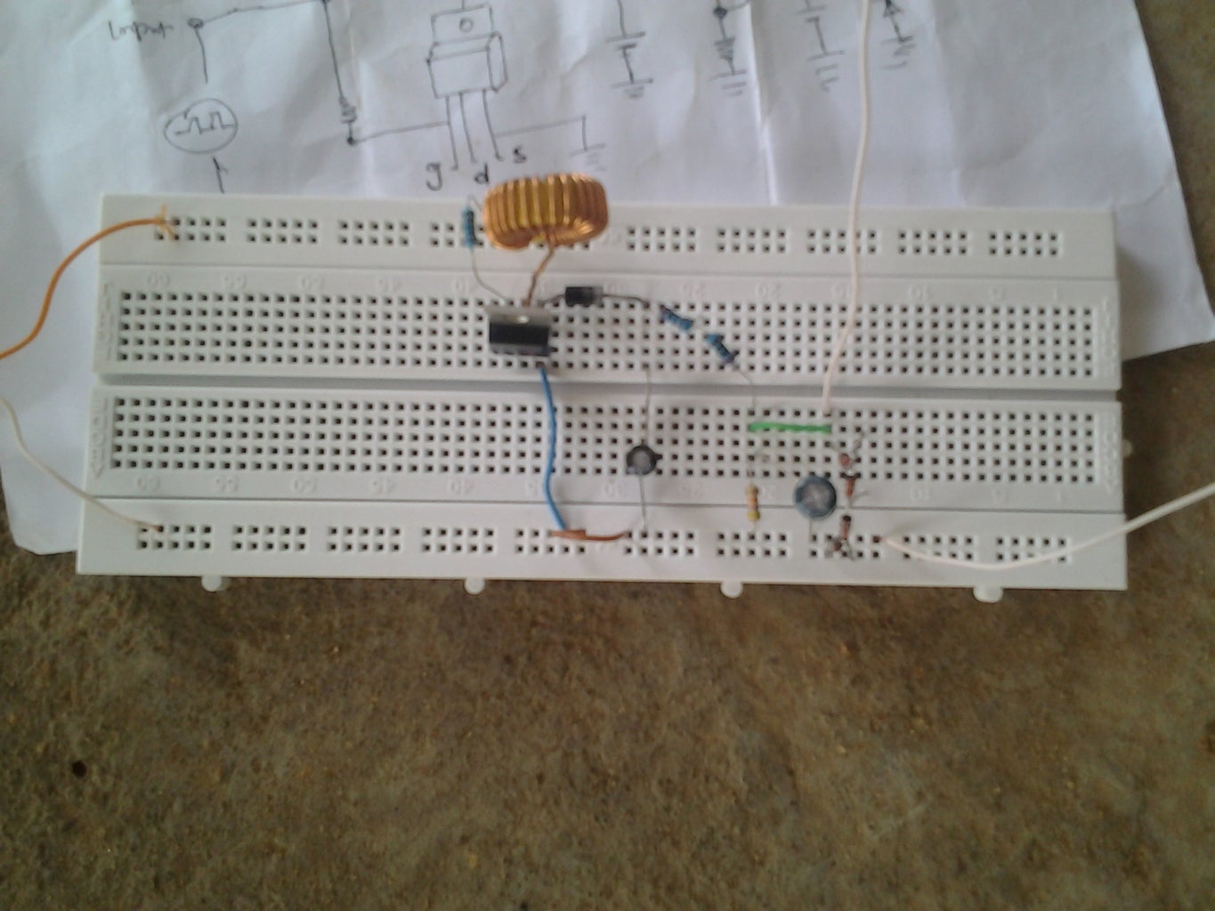
The circuit on breadboard is also show below


