

Introduction: EASY 3D Print Monitoring With ESP32 CAM


I just got my Ender3 V2 printer and I LOVE IT!
However, I'm a 'Lazy Maker'. My printer is in the far end of the basement and my home office is on the 2nd floor. The idea of constantly running up and down stairs to check on a print job's progress leaves a lot to be desired.
I have seen products like OctoPrint and other retail products and they're much more than I need. I just want to see a live video of what's happening and ideally, get an email on my phone when the job is done.
Enter the humble ESP32 CAM Module. For just $10, We get a webcam and WiFi-enabled microcontroller. Half the problem solved.
We can use the free IFTTT IoT service to send us an email when our task receives a WebHooks trigger event from the ESP32. Other half of the problem is solved.
I just modified the standard demo sketch provided by Espressif for the ESP32 CAM module, removing a lot of the settings to make a smaller interface that fits nicely on a phone screen.
The Flash LED on the ESP32 can be turned off/on remotely so you can check the progress of your job even if the lights are off in your workshop.
Fusion360 was used to design the case and ruler/switch support. The parts were printed on a Creality Ender 3 V2 with PLA.
This Instructable assumes you are quite familiar with using the Arduino IDE to program Arduinos and that you have previously worked with an ESP32 module. If you need to, install the ESP32 json line in your Arduino Preferences Screen and get the ESP32 Board Definitions.
Add this line to your Arduino Preferences/Additional URLs field:
https://dl.espressif.com/dl/package_esp32_index.json
Supplies
1 - ESP32 CAM (AI-Thinker version) module and Arduino sketch (provided)
1 - FTDI Programmer Board and USB cable to upload the sketch to your ESP32 CAM.
1 - 3D Printer End Stop Switch
1 - Small Prototype board(approx 53mm x 50mm), solder, connecting wires and 3 foot length of 2 conductor wire for the limit switch.
2 - Lengths of female terminal strip if you don't want to permanently solder the ESP32 to the board.
1 - 2 pin length of male terminal strip for the end stop switch cable.
1 - Plastic 12 inch/30cm ruler
1 - 10 K Ohm resistor
1 - Rocker power switch
1 - 5V power supply (used old iPhone charger cube and cord with the end cut off for just 5V and GND)
3D-printed case for the CAM module and frame support for the limit switch/ruler arm. (STL files provided)
Free account on IFTTT.com so you can get email notifications when your print job is done.
Step 1: Wiring the Circuit


It's recommended you wire this project up on a breadboard to get it working. Then you can transfer the components to a prototype board.
The ESP32 CAM module does not have a built in USB adapter. It's necessary to use an FTDI serial adapter to upload the sketch to the module.
The ESP32 CAM module typically uses between 80 and 180 mA to drive it. Your computer's USB Port will be powerful enough to upload the sketch, but it will not likely be able to provide enough current to actually RUN the module as a Webcam. If you try to run the camera from the FTDI adapter, you will likely get brownout warnings in the Serial Monitor and the unit will not properly run. You will need a separate 5V 1A DC power adapter to run the webcam module.
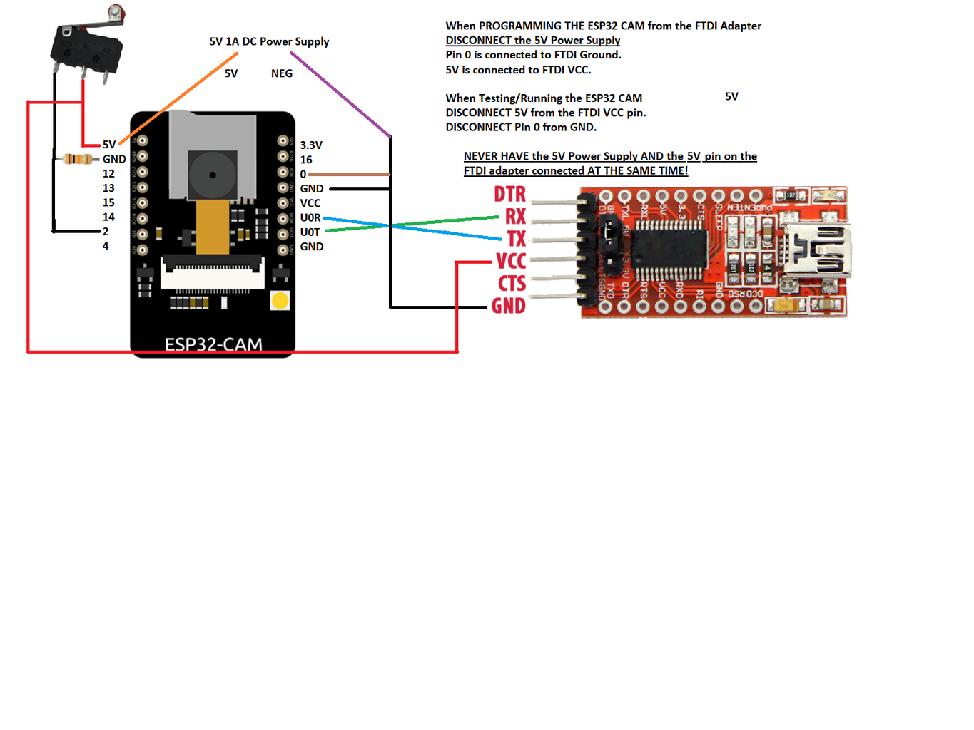
Wire up the parts as shown in the diagram.
So there are two wiring modes: 1. Sketch Upoading and 2. Webcam Operation
1. Sketch Uploading
ESP32 FTDI (with power jumper on 5V)
GND ---- GND
5V ------- VCC
IO0 ------ GND (this puts the ESP32 in programming mode)
U0T ----- Rx
U0R ----- Tx
2. Webcam Operation / Testing
ESP32 FTDI (with power jumper on 5V)
GND ------ 5V Power Supply -NEG wire
5V ------ 5V Power Supply +5V (disconnect FTDI VCC!)
IO0 DISCONNECTED from FTDI GND (It won't boot if IO0 is still connected to GND)
U0T ----- Rx
U0R ----- Tx
Keeping U0T and U0R connected to the FTDI adapter allows you to use the Arduino Serial Monitor for diagnostics and to get the IP Address of your ESP32 CAM Module and confirm it's running.
Finally the end stop switch is wired to pin 2 on the ESP32 as shown in the diagram. This switch will initiate the sending of the 'Job Done' message to your email account. It should be wired so the circuit CLOSES when the roller is pressed (ie. contact made).
REMEMBER!!!!
NEVER have the 5V power supply AND the FTDI VCC power connected to your ESP32 at the same time. Bad things will happen and you'll likely need some new parts or worse!
Step 2: Set Up IFTTT WebHooks Event and Email Task


Go to www.ifttt.com and create an account for yourself. It is free. Remember that the email address you supply at registration is the address where the 'Job Done' notification will be sent.
ENGRTUTOR on YouTube has an excellent tutorial on how to set up IFTTT with WebHooks and Email. Please refer to the tutorial here:
Look at the screen shots in this section to see how I set up my Webhook trigger and Email event.
As per the tutorial, go to the Documentation page and do a Test send of YOUR Webhook trigger to see if it sends you an email. Depending upon the time of day and the IFTTT server loads, it may take between 10 seconds and 2 minutes for you to receive your email. Please be patient.
Once you're confident your trigger is working, copy down the following information:
Your WebHooks Key (found in the Documentation button ) and
Your Trigger text ('Finished') in the screen shots but you defined your own.
We'll put these values in the ESP32 CAM sketch next.
Step 3: Modifying the ESP32 CAM Sketch With Your IFTTT and Network Settings
UPDATE JUNE 1 2023. Reload of the project based on possible issue. This version of the software has been tested as working on June 1, 2023.
The project has been provided as 4 separate files.
Create a folder called '3DPrintCamera2023'.
Download the 4 separate files into that folder.
Please make sure you've added the ESP32 boards to your Arduino IDE.
Open the project.
Modify these lines in the 3DPrintCameraInstructable tab:
const char* ssid = "xxx"; // your home network
const char* password = "xxx"; // your home wifi password
const char* host = "maker.ifttt.com";
const char* apiKey = "xxx"; // your IFTTT API key
to show YOUR IFTTT API key.
Further down in the sketch are the lines that control doing an HTML POST operation to send your IFTTT trigger event. Modify them as specified in the comments to put in your trigger event code:
// yourTrigger is your IFTTT webhooks trigger. No "" around it
String url = "/trigger/yourTrigger/with/key/";
and further down:
client.print(String("POST ") + url + " HTTP/1.1\r\n" +
"Host: " + host + "\r\n" +
"Content-Type: application/x-www-form-urlencoded\r\n" +
"Content-Length: 13\r\n\r\n" +
"value1=" + "yourTrigger" + "\r\n");
// "yourTrigger" is your IFTTT webhooks trigger. WITH "" around it
Duble-check your circuit and then connect it to your computer. Make sure you've selected the ESP32 CAM board and correct COMM port.
On your circuit, it should be in Sketch Upload mode:
1. Sketch Uploading
ESP32 FTDI (with power jumper on 5V)
GND ------ GND
5V ------ VCC
IO0 ------ GND (this puts the ESP32 in programming mode)
U0T ----- Rx
U0R ----- Tx
Upload the sketch. You may have to press the 'Boot' button that is underneath the microcontroller to initiate the upload.
After the upload is done, put your circuit in Webcam/Testing mode. DISCONNECT FTDI VCC and pin IO0 from GND.
Webcam Operation / Testing
ESP32 FTDI (with power jumper on 5V)
GND ------ 5V Power Supply -NEG wire
5V ------ 5V Power Supply +5V (disconnect FTDI VCC!)
IO0 DISCONNECTED from FTDI GND (It won't boot if IO0 is still connected to GND)
U0T ----- Rx
U0R ----- Tx
Open the Serial Monitor, set it to 115200 baud, and power up the circuit with your Power Supply. The circuit should boot and you should see a messages:
"WiFi connected
Camera Ready! Use 'http://192.168.x.y'
It may take a few resets to get it to work.
Then go to a browser and type in the URL. You should see the webcam page load.
Click the 'Start Streaming' button and your webcam should start broadcasting.
Press the 'Floodlight' switch and the flash LED should come on. WARNING! It's BRIGHT!
Try pressing the end stop switch and see if you get an email message after a bit of a wait (10 seconds to 2 minutes typically). If it's wired correctly you'll see a message in the Serial Monitor indicating the button is pressed.
If all works, you're almost done. Just have to solder up the circuit, print the 3d parts and do final assembly!
If you're good with HTML and Javascript, and wish to modify the actual webcam web interface, please visit this tutorial I provided for another project which explains how to modify the web code. The tutorial is here.

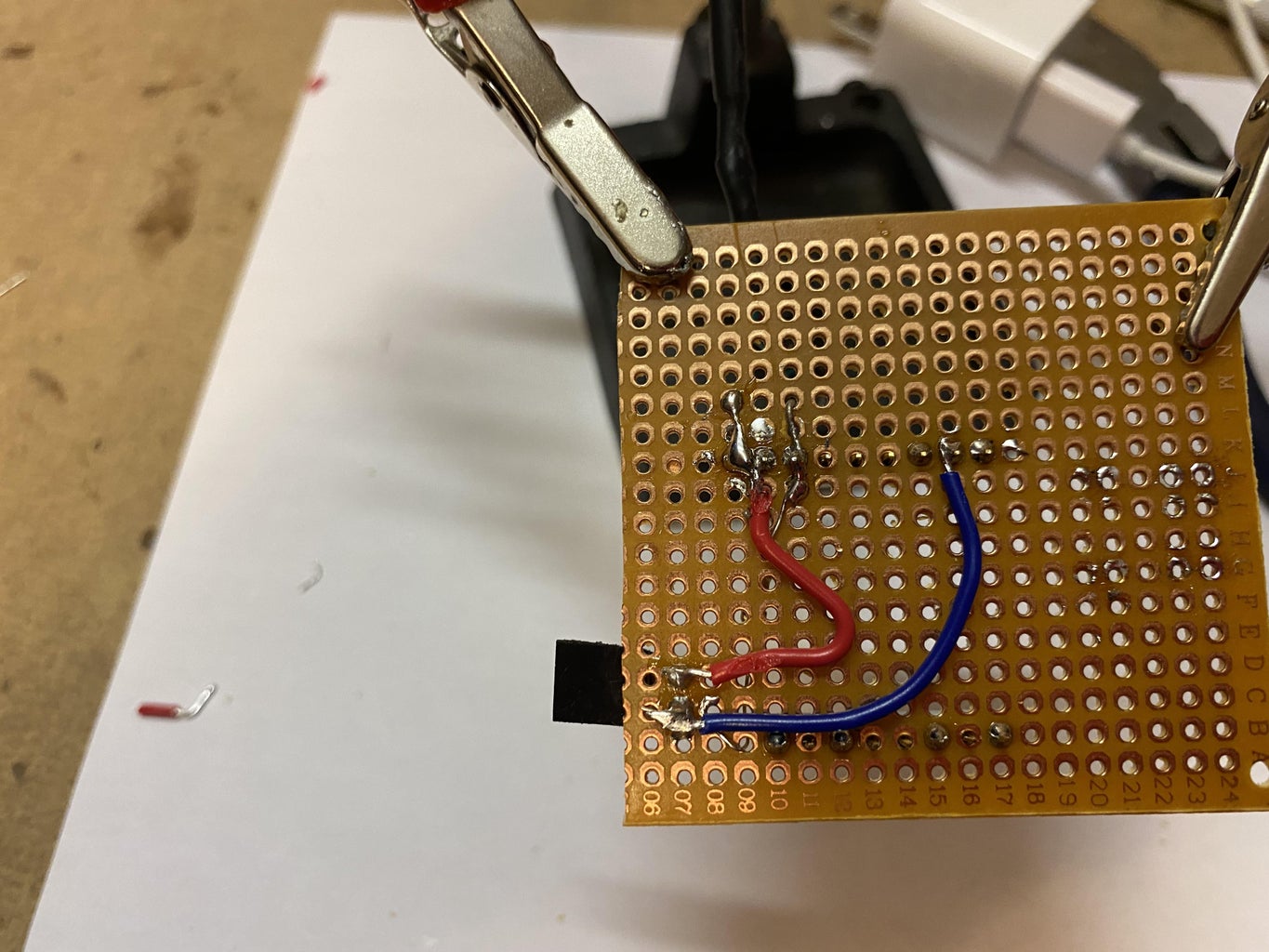
Step 4: Solder Your Circuit and Print the 3D Parts and Assemble the Webcam


You can solder up the circuit as you wish and use the 3D files as provided to print the case and lid that will fit the board and the switch support to hold the ruler with the end stop switch.
Print out the case, lid and the baseBody (ruler/switch) support on your own 3D printer.


Step 5: Modify Your Printer's Post-Processing Gcode

On the Ender 3 V2, when a job is finished, the hot end returns to X0,Y0. We need the Z-axis to rise to a pre-set height so it can press the end stop switch that will initiate the email notification event that sends you the 'Job Done' message.
For the Ender 3 V2,
1. Launch your Slicer software and get to the Manage Printers button for your software. I'm using Creality Slicer 4.8.
Navigate to your Post Processing Gcode editor for your particular printer. See the pic above for the edits made for the Ender 3 V2.
In this case, I commented out the G1 X0 Y0 command by putting a ';' in front of it.
I added,
G1 Z100 which raises the Z-axis to 100 mm height.
G4 500 which pauses the GCode for 500 milliseconds to allow the switch to fire.
G1 Z80 which lowers the Z-axis back to 80 mm height to release the switch.
Depending upon the final HEIGHT of your print job, you'll want to modify the Z-axis values so that your Z-axis rises above the job and doesn't crash back down into it.
Save the Gcode changes and exit the screens.
Step 6: Mount the Ruler/End Stop Switch Support


Here is a video for final assembly of the project. You'll see from the photos that the support is just taped to the top of the printer frame.
The end stop switch was mounted with a twisted piece of wire through two small holes drilled in the end of the ruler.
Slide the ruler up into the support.
I put tape over the viewing hole of the x-axis belt tensioner because the roller on the switch just happens to fall right into the hole. You can adjust and modify as necessary for your printer.
Use some clips to hold the switch at such a height that when the z Axis rises, it will contact the switch. This will take some measuring/adusting/testing on your part.
For myself, I just made a really small print job that took about a minute to print and then the post-processing Gcode executes and I adjust the arm as needed.
You could re-mark the ruler to indicate different stop heights for convenience.
Step 7: Final Thoughts
Depending upon where your printer is in relation to your WiFi hub, you may find the signal quality isn't that great and you get dropouts in the webcam signal.
It's possible that the stepper motors in the printer put out a lot of radio-frequency noise and that reduces the quality of the WiFi signal for the ESP32 CAM. This is noticable as static-y lines that appear on your screen as the webcam is running.
I also found that on an iPhone, the webcam doesn't always launch the video streaming if I'm using the Safari browser. I installed Chrome and it works well with no issues.
Once in a while you may find that the webcam may not start up on power on. If you look inside the case through the side slots, you can see the red LED come on and then go off after a few seconds. This typically indicates all started up correctly. If this doesn't happen, just recycle the power and it should start up.
You also would be best to use the external snap-on antenna option for the ESP32 if that's possible. I found that if I had the webcam behind the printer, I couldn't get a signal to reach the router. When I moved the webcam in front of the printer it worked much better.
I really enjoyed this project. It was CHEAP and I now have the convenience of monitoring my jobs from anywhere in my home and getting a completion email. However, my cardiovascular system is not getting the workout it would without this project's success.
I hope you find it fun and useful!
NOW GO OUT
AND
MAKE SOMETHING WONDERFUL!

Participated in the
Electronics Contest


