

Introduction: How to Modify RC CAR Via 2.4 GHz NRF24L01 Arduino Part1 Transmitter(Tx)


This instruction will introduce you how to modify cheap rc car by using 2.4 GHz nRF24L01 module with Arduino controller UNO.
Ordinary rc car toy use AM/FM 20-50 MHz radio control which have only 5-10 m. remote range and noisy control around blind area.
The instruction will advice how to modify transmission to be 2.4 GHz system that is free license radio frequency range.It's more reliable,farther remote range and less noisy.
Thank to arduino-info.wikispaces.com andgithub.com/maniacbug/RF24 for RF24 library and other nRF24L01 module information.
You can purchase electronic parts from Aliexpress, Banggod,Ebay,etc.
Project more : http://hobbywitch666.blogspot.com
Step 1: Materials & Tools


Materials
1. 1 - Arduino controller - UNO (Nano and Pro mini cannot use)
2. 1 - NRF24L01 module with SMA anttenna
3. 1 - Socket adapter for NRF24L01
4. 1 - LED 5 mm.
5. 5 - Resistor 1 kOhm. 1/4 watt.
6. 1 - Capacitor 0.1 microF 50V.
7. Dupont wires.
8. Male pin header
9. Female pin header
10. Dupont Jumper Cable Housing Male Pin Connector
11. Dupont Jumper Cable Housing Female Pin Connector
12. Heat shrink tube 2.5 mm.
13. PCB - DIY circuit board
14. Battery 9 V. 300 mAh.
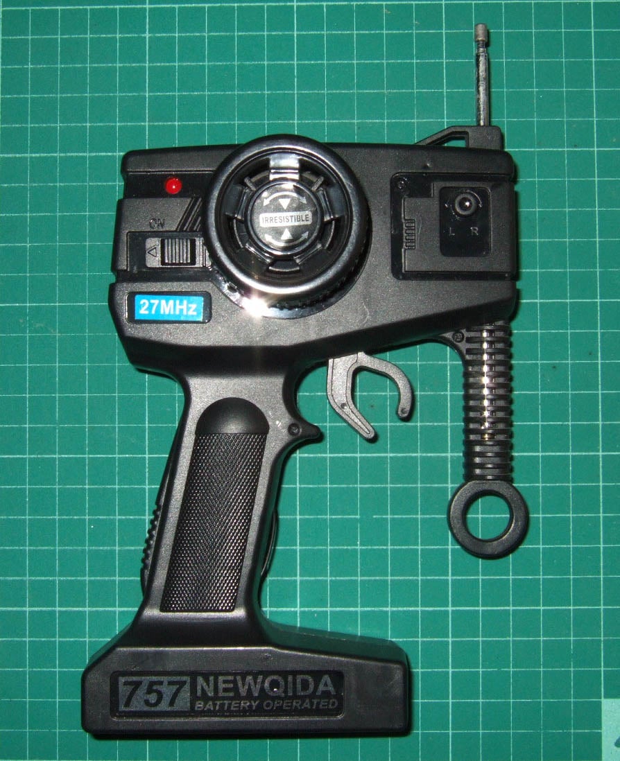
15. RC car toy transmitter(Pistol type with Steering wheel)
Tools
1. Soldering gun.
2. Soldering wire.
3. Soldering paste.
4. Screw driver.
5. Plier.
6.Hot glue gun.
7.Fixing material
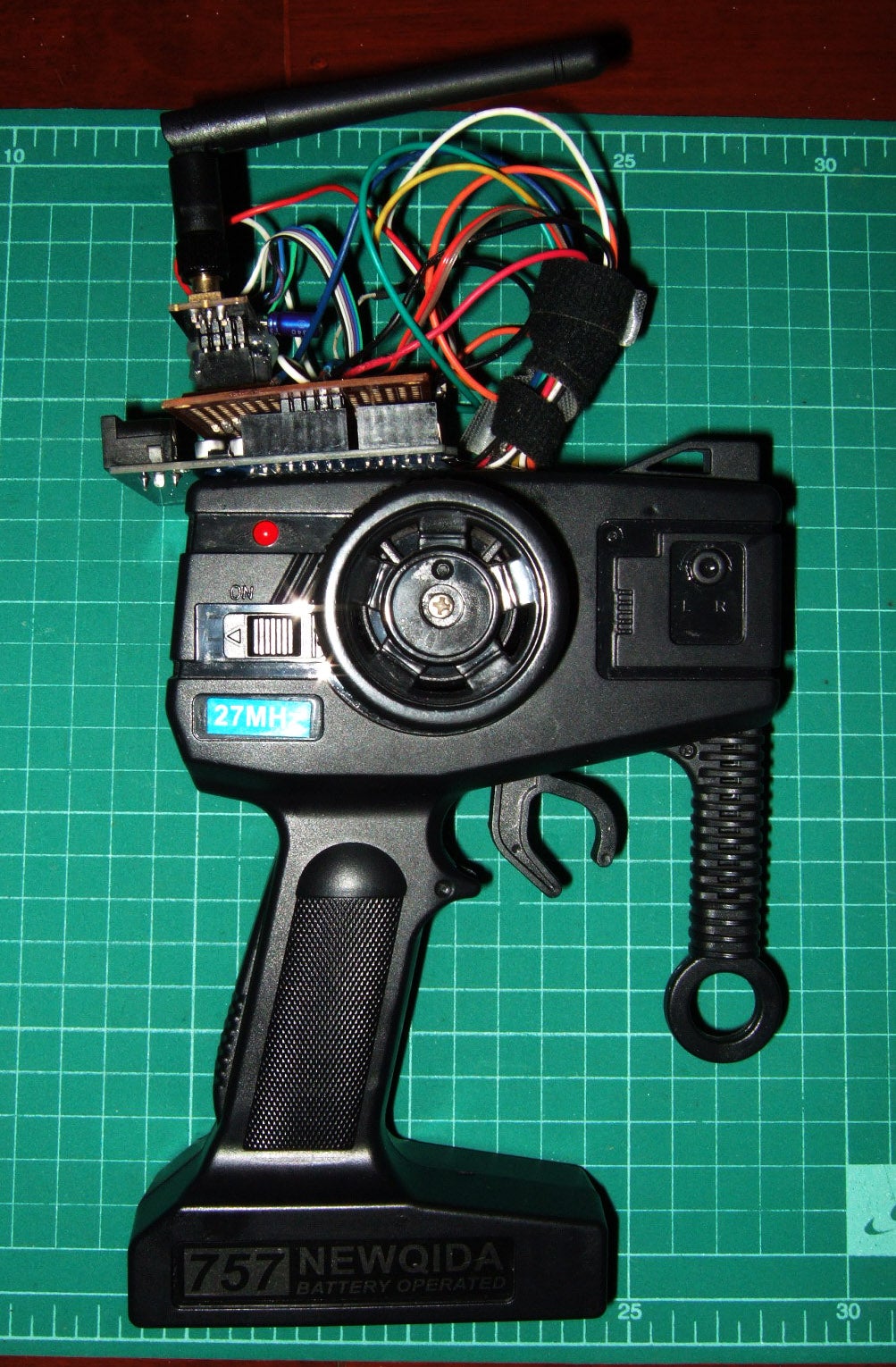
Step 2: Electronic Parts Installation & DIY Shield


RC car toy transmitter has 4 button switches to control car for 4 direction - turning right /left ,going forward/backward.
For turning right /left controlled by steering wheel like real car.For going forward/backward controlled by trigger pull-forward or push-backward.
We will use 4 button switched of transmitter to send 4 input to Arduino controller.
Look at the circuit diagram:-
Arduino UNO to Pistal Transmitter(Make DIY shield)
pin No :
3 - Turning right : steering wheel contact terminal
4 - Turning left : steering wheel contact terminal
6 - Go Forward : pulling trigger contact terminal
7 - Go Backward : pushing trigger contact terminal
Connect 3.3 V. supply to Power on status LED positive leg.Negative leg connect to resistor 1 kOhm.
* input signal use 3.3 V. supply from Arduino UNO. Do not apply 5V. It's too high voltage.(Ghost signal problem)
* take off all old existing electronic devices on circuit board otherwise it will has short circuit problem.
nRF24L01 module Socket adaptor to Arduino UNO
pin No :
Vcc - 5 V. pin (Do not connect 5V. direct to nRF24L01 module,it's supplied only 3.3V.)
GND - GND
CE - 9
CSN - 10
SCK - 13
MO - 11
MI - 12
IRQ - 2
*If you have communication problem,you can change connection from pin 13,11,12 to pin SCK,MOSI,MISO of UNO programming pins.
*It's necessary to add 0.1 microF to nRF24L01 module pin Vcc/GND because the module needs high continuous current and stable voltage.
*Soldering all devices carefully ,use enough large wire.Making good ground otherwise it will has ghost input signal.
Step 3: Software Download & Upload to Transmitter
Arduino sketch and Library :
1.Down load attached sketch file .ino and download library zip file for nRF24L01 module from https://github.com/maniacbug/RF24/downloads
*File printf.h is not necessary for 2 pipes communication.
2.Add library zip file to Arduino software.(After added you will see new library RF24-master in Examples menu.)
3.Before using new nRF24L01 modules,we shall burn the modules by uploading default sketch pingpair and GettingStarted for tuning up frequency otherwise it will has uncommunication problem.(Use another Arduino UNOs and nRF24L01 modules for pairing)
4.After matching the frequency ,we can upload Tx sketch to transmitter.(If you have problem,go to visit website https://arduino-info.wikispaces.com/Nrf24L01-2.4GH...for more information)
5.The sketch serial monitor will not show anything as the video clip,we have to build receiver(Rx) on the car.Go to next instruction"How to Modify RC CAR Via 2.4 GHz NRF24L01 Arduino Part2 Reciever(Rx)"


