

Introduction: LEGO Robot Drives Thru a Maze


This is a simple, autonomous robot designed to drive thru a maze to an exit. It is built using LEGO Mindstorms EV3. The EV3 Software runs on a computer and generates a program, which is then downloaded to a microcontroller called an EV3 Brick. The programming method is icon-based and high-level. It’s very easy and versatile.
PARTS
- LEGO Mindstorms EV3 set
- LEGO Mindstorms EV3 ultrasonic sensor. It’s not included in the EV3 set.
- Corrugated cardboard for the maze. Two cartons should be sufficient.
- A small piece of thin cardboard to help stabilize some corners and walls.
- Glue and tape to connect cardboard pieces together.
- A red greeting-card envelope to identify the exit of the maze.
TOOLS
- Utility knife to cut the cardboard.
- Steel ruler to aid the cutting process.
MAZE-SOLVING METHOD
There are several methods of navigating a maze. If you are interested in studying them, they are described very well in the following Wikipedia article: https://en.wikipedia.org/wiki/Maze_solving_algori...
I chose the left-hand wall-follower rule. The idea is that the robot will keep a wall on its left side by making the following decisions as it goes thru the maze:
- If it’s possible to turn left, do so.
- Otherwise, go straight if possible.
- If it can’t go left or straight, turn right, if possible.
- If none of the above are possible, this must be a dead end. Turn around.
One caution is that the method could fail if the maze has a loop in it. Depending on the placement of the loop, the robot could keep going around and around the loop. A possible solution for this problem would be for the robot to switch to the right-hand wall-follower rule if it realized that it was going in a loop. I didn’t include this refinement in my project.
STEPS FOR BUILDING THE ROBOT
Although LEGO Mindstorms EV3 is very versatile, it allows no more than one of each type of sensor connected to one Brick. Two or more Bricks could be daisy-chained, but I didn’t want to buy another Brick, and so I used the following sensors (instead of three ultrasonic sensors): infrared sensor, color sensor, and ultrasonic sensor. This worked out well.
The pairs of photos below show how to build the robot. The first photo of each pair shows the parts needed, and the second photo shows the same parts connected together.
Step 1: Base of the Robot


The first step is to build the base of the robot, using the parts shown. The robot base is shown upside-down. The small L-shaped part at the back of the robot is a support for the back. It slides as the robot moves. This works okay. The EV3 kit doesn’t have a rolling-ball-type part.
Step 2: Top of the Base


The next 3 steps are for the top of the base of the robot, the color sensor, and the cables, which are all 10 inch (26 cm) cables
Step 3: Infrared and Ultrasonic Sensors


Next, are the infrared sensor (on the left side of the robot) and the ultrasonic sensor (on the right). Also, the 4 pins for attaching the Brick on top.
The infrared and ultrasonic sensors are located vertically instead of the normal horizontal. This provides better identification of the corners or ends of the walls.
Step 4: Cables

Attach the Brick and connect the cables as follows:
- Port B: left large motor.
- Port C: right large motor.
- Port 2: ultrasonic sensor.
- Port 3: color sensor.
- Port 4: infrared sensor.
Step 5: Final Step in Building the Robot: Decoration


The wings and fins are only for decoration.
Step 6: Pseudocode for the Program
- Wait 3 seconds and say “Go.”
- Start the robot moving straight ahead.
- If it’s possible to turn left (i.e., if the infrared sensor does not sense an object nearby), say “Left” and go left.
- Go forward about 6 inches (15 cm) to avoid a false left turn. The reason is that after the robot has turned, the sensor would see the long space it had just come from, and the robot would think it should turn left, which is not the proper thing to do. Go back to step 2.
- If it’s not possible to turn left, check what the Color Sensor sees ahead of the robot.
- If there is no color (i.e. no object), then go back to step 2.
- If the color is Red, this is the exit. Stop the robot, play a fanfare, and stop the program.
- If the color is Brown (i.e., brown cardboard ahead), then stop the robot.
- If it’s possible to turn right (i.e., if the ultrasonic sensor does not sense an object nearby), say “Right” and go right. Go back to step 2.
- If it’s not possible to turn right, say “Uh-oh”, back up about 5 inches (12.5 cm), and turn around. Go back to step 2.
Step 7: Program

LEGO Mindstorms EV3 has a very convenient icon-based programming method. Blocks are shown at the bottom of the display screen on the computer and can be drag-and-dropped into the programming window to build a program. The screen shot shows the program for this project. The Blocks are described in the next step.
I couldn’t figure out how to set up downloading of the program to you folks, and so the Blocks are described in the next step. Each Block has options and parameters. It’s very easy and versatile. It shouldn’t take much time for you to develop the program and/or change it to suit your needs. As always, it’s a good idea to save the program periodically when developing it.
The EV3 Brick may be connected to the computer by either a USB cable, Wi-Fi or Bluetooth. When it’s connected and turned on, this is indicated in a small window in the lower right-hand corner of the EV3 window on the computer. The “EV3” in the right-most side turns red. When this display is set to Port View, it shows in real time, what each sensor is detecting. This is useful for experimenting.
When building this program, I would suggest to work from left to right and top to bottom, and to enlarge the Loop and Switch Blocks before dragging other Blocks inside. I ran into messy problems trying to insert additional Blocks inside before enlarging.
Step 8: Program Blocks
- Starting at the left side of the program, the Start Block is present automatically when a program is being developed.
- Next is a Wait Block, to give us 3 seconds to place the robot at the entrance to the maze, after initiating the program.
- A Sound Block makes the robot say “Go.”
- A Loop Block contains most of the program. The display should be zoomed out 4 or 5 times and this Loop Block should be enlarged almost to the right edge of the Programming Canvas before you start inserting Blocks. It can be made smaller afterwards.
- The first Block inside the Loop is a Move Steering Block with the Steering set to zero and the Power set to 20. This starts the motors running straight ahead at low speed. A faster speed would make the robot move too far when it continues ahead while speaking in subsequent steps.
- A Switch Block in the Infrared Sensor Proximity Mode checks if there is any object farther than a value of 30. This is equivalent to approximately 9 inches (23 cm) for brown cardboard. If the value is greater than 30, then Blocks 7, 8 and 9 are executed, else the program goes to Block 10 below.
- A Sound Block makes the robot say “Left.”
- A Move Steering Block with the Steering set to -45, Power set to 20, Rotations set to 1.26, and Brake at End set to True. This makes the robot turn left.
- A Move Steering Block with the Steering set to zero, Power set to 20, Rotations set to 1.2, and Brake at End set to True. This makes the robot go forward about 6 inches (15 cm) to avoid a false left turn.
- A Switch Block in the Color Sensor Measure Color Mode checks what color is ahead of the robot. If there is no color (i.e. no object), then the program goes to the end of the loop. If the color is Red, then Blocks 11, 12 and 13 are executed. If the color is Brown, the program goes to Block 14 below.
- A Move Steering Block in Off Mode to stop the motors.
- A Sound Block plays a fanfare.
- A Loop Interrupt Block exits the Loop.
- A Move Steering Block in Off Mode to stop the motors.
- A Switch Block in the Ultrasonic Sensor Compare Distance Inches Mode checks if there is any object farther than 8 inches (20 cm). If it’s more than 8 inches, then Blocks16 and 17 are executed, else the program goes to Block 18 below.
- A Sound Block makes the robot say “Right.”
- A Move Steering Block with the Steering set to -55, Power set to -20, Rotations set to 1.1, and Brake at End set to True. This makes the robot turn right.
- A Sound Block makes the robot say “Uh-oh.”
- A Move Tank Block with Power Left set to -20, Power Right set to -20, Rotations set to 1, and Brake at End set to True. This makes the robot back up about 5 inches (12.5 cm) to make space to turn around.
- A Move Tank Block with Power Left set to -20, Power Right set to 20, Rotations set to 1.14, and Brake at End set to True. This makes the robot turn around.
- At the exit of the Loop is a Stop Program Block.
Step 9: BUILD a MAZE


Two corrugated cardboard cartons should be sufficient for the maze. I made the maze walls 5 inches (12.5 cm) high, but 4 inches (10 cm) should work just as well if you’re short of corrugated cardboard.
First, I cut around the walls of the cartons, 10 inches (25 cm) from the bottom. Then I cut around the walls 5 inches from the bottom. This provides several 5-inch walls. Also, I cut around the bottoms of the cartons, leaving about 1 inch (2.5 cm) attached to the walls for stability.
The various pieces can be cut and glued or taped wherever needed to form the maze. There should be a 12 inch (30 cm) space between the walls in any path with a dead end. This distance is needed for the robot to turn around.
Some of the corners of the maze may need to be reinforced, Also, some straight walls need to be kept from bending if they include a straightened carton corner. Small pieces of thin cardboard should be glued to the bottom at those places, as shown.
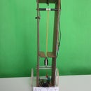
The exit has a red barrier consisting of half a red greeting-card envelope and a base made from 2 pieces of thin cardboard, as shown.
One caution is that the maze should not be large. If the robot’s turns are at a slight angle from the proper one, the discrepancies add up after a few turns. For example, if a left turn is 3 degrees off, then after 5 left turns the robot is going 15 degrees off. A large maze would have more turns and a longer path than a small one, and the robot could run into the walls. I had to fiddle several times with the Rotations settings of the turns in order to get a successful drive thru even the small maze I made.
FUTURE ENHANCEMENTS
An obvious follow-on project is to make the robot able to determine a direct path thru the maze while navigating it, and then drive this direct path (avoiding dead-ends) right afterwards.
This is much more complicated than the current project. The robot must remember the path it has travelled, remove dead-ends, store the new path, and then follow the new path. I plan to work on this project in the near future. I expect it’s possible to accomplish with LEGO Mindstorms EV3 using Array Operations Blocks and some math-related Blocks.
CONCLUDING REMARK
This was a fun project. I hope you also find it interesting.


