

Introduction: Make It So! Star Trek TNG Mini Engineering Computer


Overview
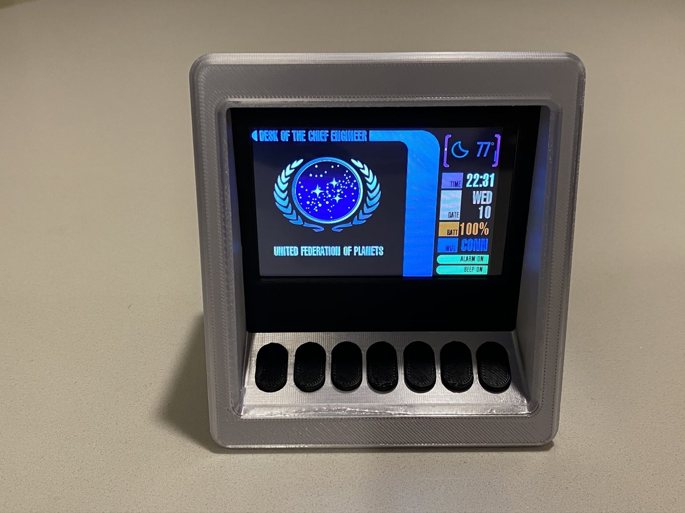
I grew up watching Star Trek: The Next Generation. I've always wanted to build a Star Trek themed device, so I finally got around to remixing one of my old projects to make a Star Trek Display Terminal.
The terminal provides the following information:
- Weather - using the National Weather Service
- Indoor Temperature, Humidity and Volatile Organic Compound (VOC) strength
- News Articles - from News.org
- Schedule (with alarm function) - from Microsoft Outlook
- Fitness Information (Steps, Move Minutes, Heart Points, Weight, Calories Burned) - from Google Fitness
- a Resistor color code chart
- an LED Resistor Calculator (to determine the resistor value based on current and source power)
- Power and Current Measurement tool
This information is made available through a combination of APIs and hardware sensors. I leverage an ESP32 for the microcontroller, and leverage the AWS Cloud for all of the data collection and aggregation.
I also included a few "easter eggs":
- Ron McNair homage - Dr McNair is the reason I became an engineer; he grew up 45 mins from my hometown. He died in the Challenger explosion.
- The name of my star ship is the "USS Ronald E McNair"
- The Registry Number is from Sr McNair's birth date; the Prefix Code is the day he lost his life.
- The use of a "prefix code" is a nod to Star Trek: Wrath of Khan (the greatest Star Trek movie of all time; don't @ me).
- The numbers of the right of the terminal case refer to my fraternity (1906 - Alpha Phi Alpha) and my alma mater and field of study - (University of Oklahoma, College of Engineering)
You have the option of customizing the numbering, lettering, and ship name, registry, etc for your own "easter eggs".
Background
Last year, I needed a low cost way to measure power and battery drain for a wearable project. I purchased an Adafruit INA219 Featherwing, and used some assorted spare parts to build a simple Power Measurement device (you can read more about it here).
This year, I decided to upgrade the device... to make it more "techy". I originally planned to build a working Star Trek tricorder (the Mark IV TR-590 Mark IX version, for those that care)... but I quickly realized that it made more sense to create something that would sit on my desk (I mean, why go to all this trouble to make a cool device, just to close it up and put it in a drawer when not used).
So, I I turned to making a version of the computer displays that you see on Star Trek TNG or Voyager (or the assorted movies). I toyed around with different designs, then came across a version created by the Ruiz Brothers of Adafruit. Adafruit does a great job of provided source files for their 3D printed projects, so I was able to take their original version and remix it for my hardware, buttons, and other peripherals.
Things to know before your proceed
- I provide step by step instructions for making my version of the project; however, I do not go into details on certain steps (I'll link to supporting instructions or documentation)
- This is a complex project. It's a "multi-disciplined make", that requires the following skills
- Arduino IDE
- AWS - You will need an account and will need to understand S3, Lambda, and Node JS
- Soldering
- 3D Printing
- There are optional "add ins" to enhance the project in order to get Calendar and Fitness information. The functionality is included in the codebase; however you will have to create "apps" in the Azure and Google clouds to support the features.
- This is ultimately customizable... you can swap out the Current Sensor with another featherwing You can use a different feather/wifi combination.
Supplies
Electronic Components
- Adafruit ESP32 Huzzah Feather
- Adafruit Featherwing Tripler Mini Kit
- Adafruit 12-Key Capacitive Touch Sensor Breakout
- Adafruit TFT FeatherWing - 3.5" 480x320 Touchscreen
- Adafruit BME680 - Temperature, Humidity, Pressure and Gas Sensor
- DC Panel Mount 2.1 Barrel Jack (2)
- Lithium Ion Polymer Battery - 3.7 V 500mAh
- Piezo Buzzer
- Mirco USB cable and 5V charger (a typical USB phone charger will work)
- Copper Foil Tape with adhesive
- Optional - Adafruit INA219 Featherwing
- Optional - 2.1 Male plugs - (for use with the INA219 Current Sensor)
Link to all electronic components except 2.1 plugs: http://www.adafruit.com/wishlists/505926
3D Filament Components And Optional Paint/Sanding Components
- Proto Pasta Conductive PLA
- Additional 3D filaments - I used 4 colors - Grey, Black, Aqua (light blue) and White
- .25 and 0.4 mm nozzles (I used the 0.25 for the lettering details).
Hardware Assembly Components and Tools
- M2x5 and M3x5 Screws
- Straight and Right Angle Header Pins (See Adafruit wishlist for links)
- Soldering Iron (and spool of solder, tip tinner, solder sucker, etc.)
- Philips Head Screwdriver Kit
- Shrink Wrap
- Stranded Wire 22AWG - five or six colors
- Solid Wire 22AWG - five or six colors
- PCB Vise and Helping hands (optional, but makes soldering easier)
- Diagonal Wire Cutters
- Wire Strippers
- Xacto Knife (for removing supports from 3D printer parts)
- 3D Printer (if you plan to print yourself)
- Putty or tape (to affix the battery to the inside of the printed case)
- Digital calipers
- Krazy Glue
- Optional - Nitrile Disposable Gloves
- Optional - Soldering Mat (optional, but protects surfaces)
Note: if you don't have these tools, I suggest you check out Becky Stern's site for recommendations for good options.
Software
Step 1: Download, Modify Files, and Print 3D Files
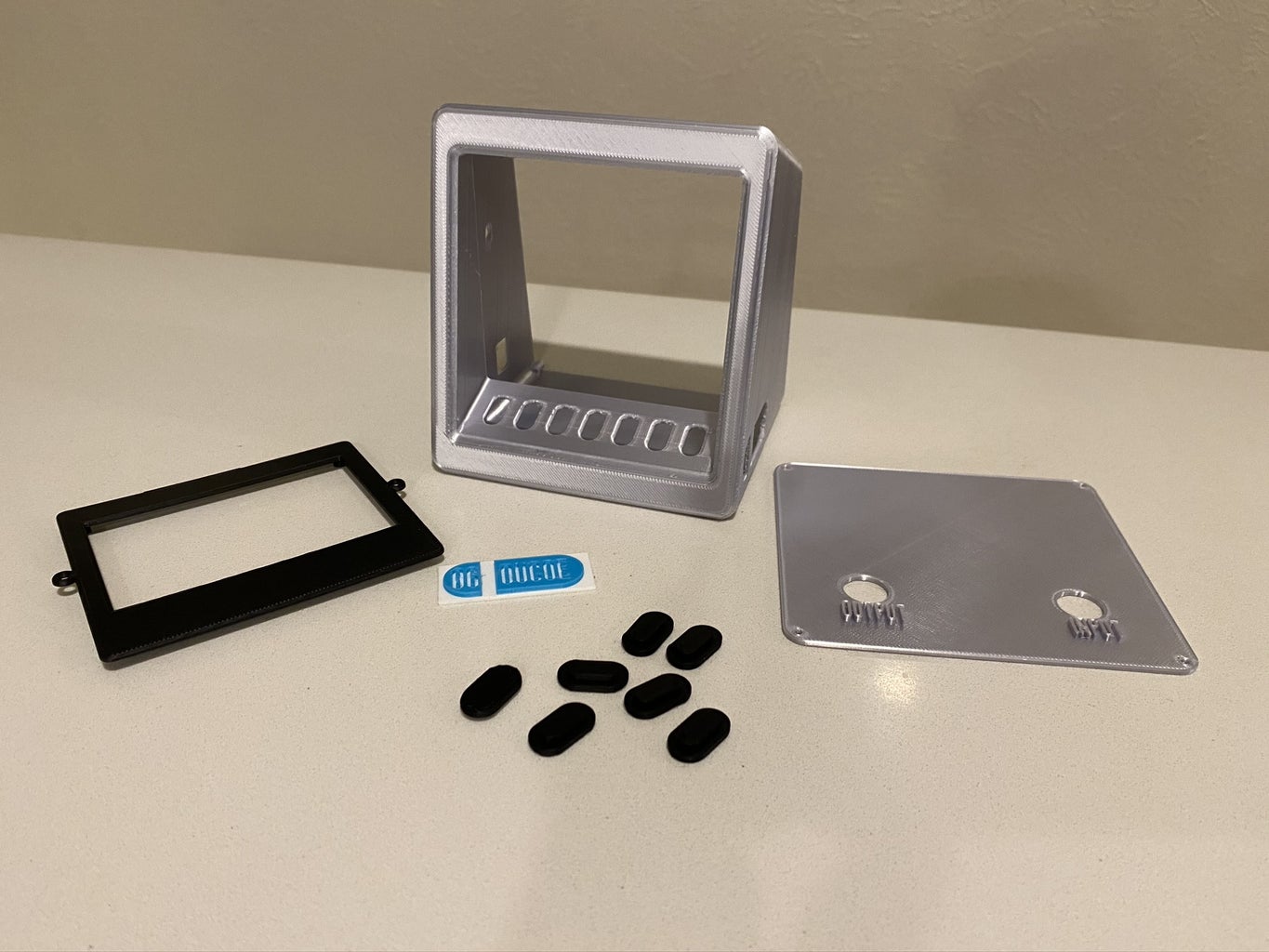


You can submit the files to a 3D printing service (like 3D Hubs) or you can print your own. Files are available at PrusaPrinters.org.
This case is a remix of the Py Portal Alarm Clock featured on Adafruit website. My project uses a similar TFT so, I was able to minimize the amount of design work needed to make the case work with my accessories.
I used the following settings for printing:
- Front and Back- printed at 0.2mm Layer Height with a 0.4mm nozzle, no supports
- Side Number - printed at 0.10mm Layer Height with a 0.25mm nozzle, no supports
- Keys - printed at 0.2mm Layer Height with a 0.4mm nozzle. You will need to print 7 and you will need to print with Proto-Pasta Conductive Filament.
- Case - printed at 0.2mm Layer Height.
- Supports are needed, but are not needed everywhere (only on the sides and the middle where the keypad sits
A few things you should know:
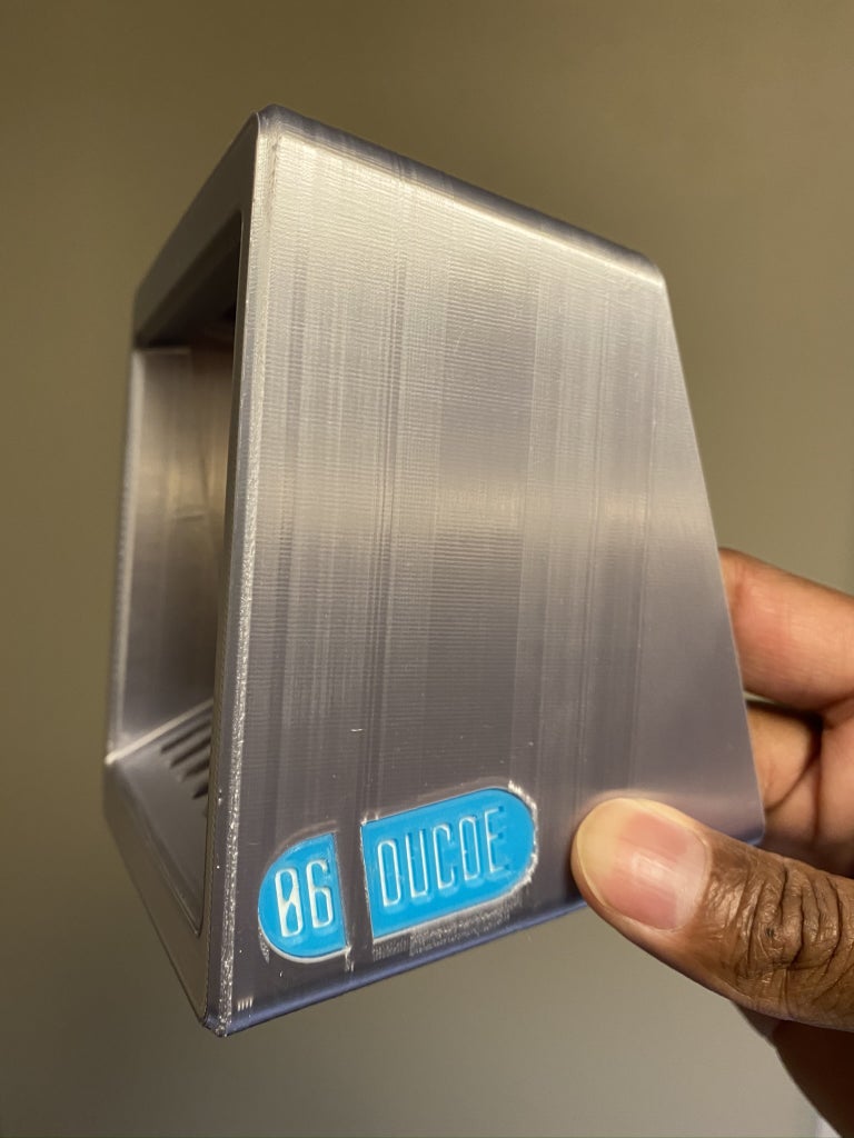
- The Prusa MK3 allows you to change colors at different layer heights. I used this feature for the side-number piece.
- Also, in regards to the side-number piece:
- The Star Trek TNG production crew would sprinkle easter eggs in the props. If you look closely at various plaques and panels, you'll see people names, song lyrics, etc. I wanted to create my own "easter egg" for the side number, so I use "06" - which refers to my fraternity (formed in 1906), and "OUCOE" - which refers to my alma mater (University of Oklahoma, College of Engineering).
- I created a "blank" side_number piece that you can modify in order to make your own custom number and text.
Step 2: Solder/Assemble Components - Part a (Keypad and Side Number)


First, we'll affix the side number. Use a small dab of glue to put the side number in place.
Next, we'll assemble the keypad.
- You'll need to cut 7 pieces of stranded wire - each between 10-12 inches in length. These will be connected to Pins 0-6 of the capacitive touch sensor. I suggest you use different colors (and write the colors/pin mapping down, as you'll need this information later). I used the following color combination:
- Yellow - Pin 0/Button 1
- Gray - Pin 1/Button 2
- Red - Pin 2 /Button 3
- Blue - Pin 3 //Button 4
- Green - Pin 4 //Button 5
- White - Pin 5 //Button 6
- Black - Pin 6 //Button 7
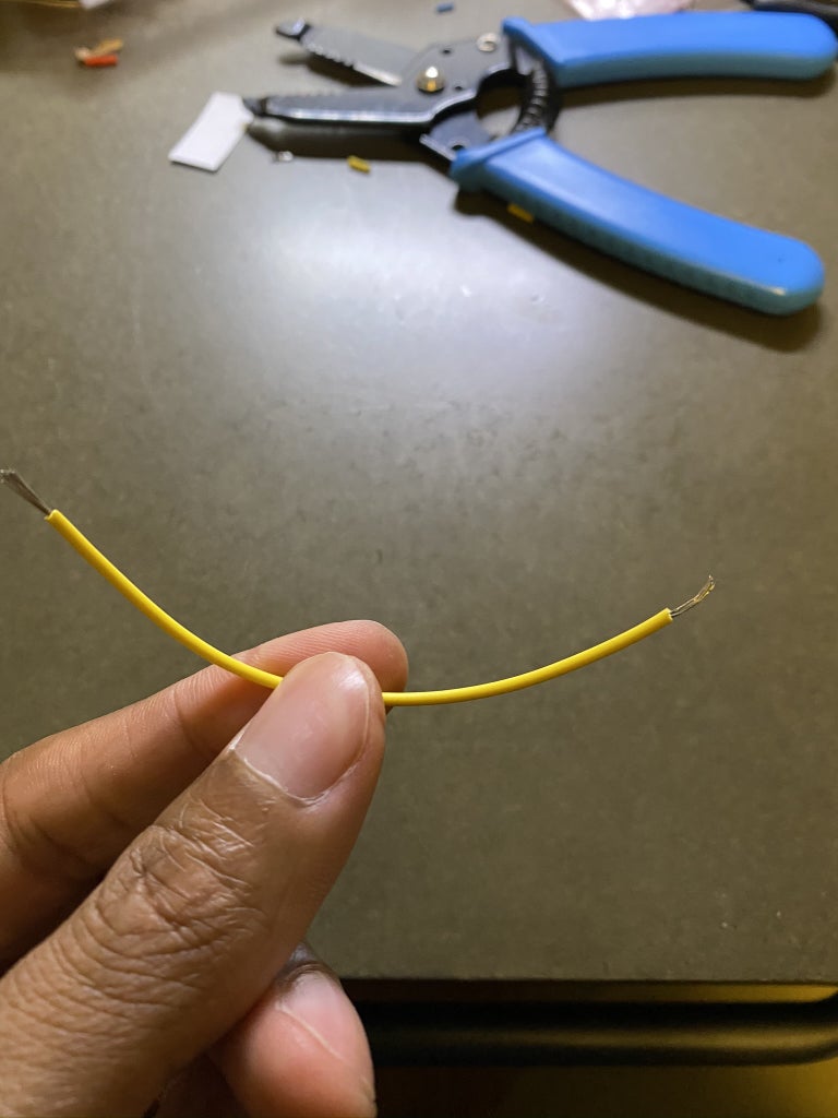
- Strip 1/2 in from the end of each wire.
- Cut 7 pieces of conductive tape (each about 1/2 inch in width) and solder the wires to the copper side of the tape.
- Remove the adhesive backing and stick them to the bottom of the keys. You may need to trim off some of the copper tape.
Note: the Keys can either be glued from the bottom (so that they are flush with the top) or glued from the top (so that they "float" a few mm from the top). I chose to glue mine from the top.
Once you've completed all 7, use a small dab of glue affix the keys to the keypad. I find it easier to:
- First "snake" the wire through the key hole.
- Then put a small dab of glue on the ridge/rim of the key
- Quickly put the key in place.
Note: Krazy Glue works best here; you may want to use gloves to limit accidents and chances of skin irritation.
Step 3: Solder/Assemble Components - Part B (Featherwings and Sensors)


The next step is to prepare and assemble the hardware components. Ultimately, this means soldering header pins and wires for later use. This guide assumes that you're comfortable with soldering; if not, check out this "Guide to Excellent Soldering" from Adafruit.
First we'll prepare out materials. For this step, you'll need:
- TFT 3.5 Featherwing
- ESP32 Feather
- INA219 Featherwing
- Tripler Featherwing
- MPR121 Capacitive Touch Sensor
- BME680 Sensor
- Straight and Right Angle Header pins
- Solid and Stranded Wire
- Soldering Tools and Helping hands
- Diagonal Wire cutters and wire strippers
- Calipers
Note: I suggest you first read through this step and cut all your wires and headers before you start soldering. That way, you won't have to stop to measure/cut.
Prepare the TFT 3.5 Featherwing
The TFT is ready to use out of the box with the only one adjustment. You'll need to solder a wire between the "Lite" pad and a pin solder pad. Our code uses ESP32 Pin 21 to control the TFT lite. Arrange the TFT the "long" way, with the reset button at the bottom. Pin 21 will be the bottom left pin.
Cut a 40mm piece of stranded wire. Strip the ends so that a few millimeters of wire are showing on each end. Using your soldering iron, carefully solder to both pins.
Note: you only need about 35mm of length... so you can trim your wire as needed. Also, I find that adding solder to the pad, then to the wire, then soldering the wire to the pad is the easiest approach. Finally - these pads are small... if you're uncomfortable, you can always skip this step: it's only for turning off the TFT with the keypad.
Prepare the ESP32 Feather
You'll need to solder standard male header pins to the ESP32. Your ESP32 should come with the headers, though you may need to trim them to get to the correct length (16 pins on the long side; 12 pins on the short side). Header pins are made to "snap away", so you can use your diagonal cutters to clip the headers to the correct length. Again, Adafruit has great instructions on how to do that, so check it out if you need guidance.
OPTIONAL - Prepare the INA219 Featherwing
First, solder male headers to the featherwing (using the same instructions as used for the ESP32). Next cut four 20mm lengths of stranded wire. I would make 2 BLACK and the others a different color. I used GRAY and BLUE for my color choices.
Strip the ends of the wire so that 3-4mm of copper wire is exposed on each end. You'll solder one each of each wire as below:
- GRAY -> V+ (plus)
- BLUE -> V- (minus)
- BLACK -> GND (ground)
- BLACK -> GND (ground)
Leave the other ends of the wires at this time; we'll ultimately solder them to the DC 2.1 plugs.
Attach the Piezo Buzzer
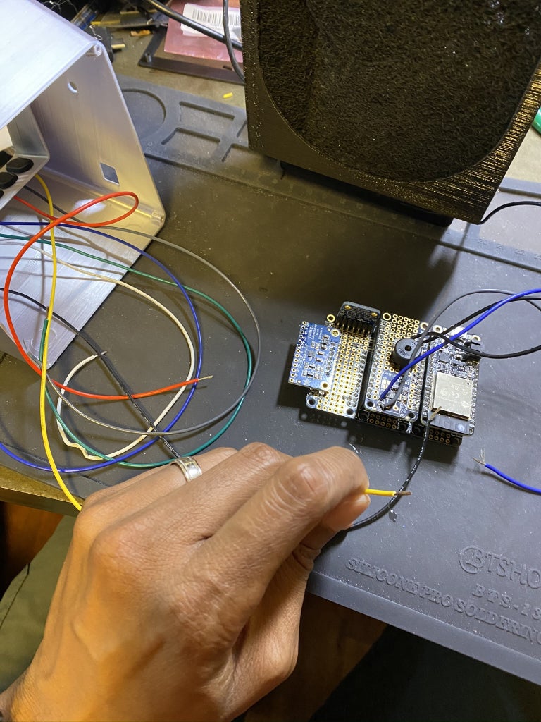
The INA Featherwing comes with a small prototyping area; we'll use that to attach our piezo. The piezo will give our project the ability to beep and sound alerts, alarms, etc.
The piezo connects to ESP32 PIN 13; this correlates to the pin next to the USB pin on the featherwing (see image for arrows). The other piezo pin connects to ground. The pieze pins are long enough to solder them directly to the featherwing... you'll just need to bend the pins into a "bow-legged man" shape (see image). Once you have the pins in place, use a helping hands (or tape) to hold the piezo in place, and solder from the underside of the featherwing.
Note - If you do not use the INA219, then you'll need to solder the piezo directly to the featherwing board.
Prepare the Tripler Featherwing
The featherwing saves us a lot of soldering; it can hold 3 feathers/featherwings... so we'll use it to make electrical connections between the TFT, ESP32, INA219 (as well as the piezo and the TFT Lite pin).
To make the connections properly, we'll need to solder two pairs of stacking headers and one pair of standard male headers.
- The regular male headers will go on in the "top" spot, but will be soldered to the bottom side of the Tripler.
- The two stacking headers will be soldered in spots 2 and 3, on the top side of the Tripler.
This is a little confusing, so be sure to look at the images to understand where each header is placed. Also, a combination of a PCB Vise and Helping Hands can greatly aid in soldering the components.
Prepare the BME 680 Sensor and the MPR121 Capacitive Touch Sensor
The last two sensors are the most difficult the attach. We need to attach header pins to the breakout boards before finalizing the assembly.
The BME Sensor is attached at a 90 angle, so that I can align the sensor to a hole in the case (so that the sensor can capture temperature, gas, humidity). You'll need to solder right angle pins to the holes. See the images to ensure you align them correctly.
The Capacitive Touch sensor is straightforward - just solder straight male connectors pins, as outlined here. Note: you SHOULD NOT solder pins to the Capacitive Touch Pins (0 - 11).
Attach BME 680 and MPR121 Sensors to Tripler Board
Both Sensors communicate via I2C... which means we only need to make 4 connections between the breakout boards and the Featherwing. For simplicity, I solder all connections between the boards.
BME 680
For this sensor, I use Helping Hands and a PCB Vise to hold both components in place (see image above). The BME680 Sensor should be placed at the end of the featherwing. See the images above to confirm placement.
The process of soldering the connections is tedious, so go slowly. I use solid core wire for the connections:
- BLACK - GND
- RED - VIN
- YELLOW - SCL (SCK pin on the sensor to the
- ORANGE - SDA (SDA pin on the sensor)
Note: The SCL and SDA pins are needed for both sensors, so it might be easier to use a SCL or SDA pin on another part of the Featherwing.
MPR121
Helping hands also help when soldering this sensor in place (tape works as well). The code used I2C for communication to the ESP32, so you'll be connecting the SCA and SDA pins.
Step 4: Solder/Assemble Components - Part C (Keypad to Capacitive Sensor and Feathewing in Case)


You'll solder the wires from the Keypad to the Capacitive Touch sensor in this step. Use the same color mapping from earlier. If you followed my color scheme, then you'll solder the colored wires as follows:
- Yellow - Pin 0/Button 1
- Gray - Pin 1/Button 2
- Red - Pin 2 /Button 3
- Blue - Pin 3 /Button 4
- Green - Pin 4/Button 5
- White - Pin 5/Button 6
- Black - Pin 6/Button 7
Once soldering is done, use a twisty-tie to hold the wires in place.
Next, screw the TFT screen to the "Front" piece. You'll use the M3 screws (four total). Once the TFT is in place, screw the "Front" piece to the case. Again, you'll use M3 screws (two).
Next, plug the Featherwing Tripler, with the all components plugged in, to the TFT.
Note - If you plan to use a battery, be sure to plug it into the ESP32-JST port before inserting the TFT. Use tape to affix the battery to the inside bottom of the case.
Step 5: OPTIONAL - Solder/Assemble Components - Part D (INA219 Feather)
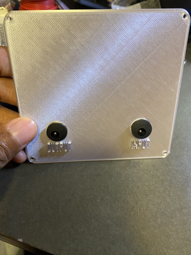


If you are using the INA219 sensor, then this is where you attach the wires to the DC plugs.
- Insert the DC plugs to the back cover, and screw them in place.
- Use a soldering iron to connect the INA219 wires.
- The Black wires should go to the GROUND for each DC plug.
- The Gray wire should go to the INPUT DC plug
- The Blue wire should go to the OUTPUT plug.
Step 6: Screw on Back Cover and Plug in USB
The final step in hardware assembly is to screw the back cover in place - using M2 screws (4). From there, plug in the USB cable, connect it to your PC, and proceed to software steps!
Step 7: Prepare AWS Environment

As I stated in the intro, the premise of the solution is as follows:
- The Terminal, powered by an ESP32, uses an MQTT (over Wifi) connection to communication with the AWS cloud.
- The AWS cloud does the bulk of the processing and serves as a relay between the Monitor and the requested services.
There are a few things we'll need to do in this step:
First, you need to set up your AWS environment, if you haven't yet. This instructable assumes you have an AWS Account already set-up, so instructions on setting up a cloud account are not included. That being said, the steps are straight-forward and can be found here.
Once you're past that step, you need to create a few services, so log into the AWS console.
Create a Thing and Download Keys
AWS IoT Core facilitates the communication between the AWS cloud and the display. You'll need to create a "thing" and download certificates to support the communication.
[Note: most of these instructions were taken from a guide written by Moheeb Zara, AWS Evangelist]
- Open the AWS console and select AWS IoT Core.
- In the AWS IoT console, choose Register a new thing, Create a single thing.
- Name the new thing "starTrekESP32". Leave the remaining fields set to their defaults. Choose Next.
- Choose Create certificate. Only the thing cert, private key, and Amazon Root CA 1 downloads are necessary for the ESP32 to connect. Download and save them somewhere secure, as they are used when programming the ESP32 device.
- Choose Activate, Attach a policy.
- Skip adding a policy, and choose Register Thing.
- In the AWS IoT console side menu, choose Secure, Policies, Create a policy.
- Name the policy AllowEverything. Choose the Advanced tab.
- Paste in the following policy template.
- { { "Version": "2012-10-17", "Statement": [ { "Effect": "Allow", "Action": "iot:*", "Resource": "*" } ] }
- Choose Create. (Note: This is only recommended to getting started. After you are comfortable with everything working, please go back and change this to something more restrictive.)
- In the AWS IoT console, choose Secure, Certification.
- Select the one created for your device and choose Actions, Attach policy.
- Choose AllowEverything, Attach.
Before you leave, click on "Settings" (on the left menu). Your "Custom endpoint" will be shown; save that to a text file... you'll need it when you configure the ESP32.
Create a Blank Lambda file
Lambda is a form of serverless compute, so we don't have to worry about any hardware here. Ultimately, this is where we'll place our updated code (which we'll do it a few steps). For now, we just want to create a placeholder, so...
- Log back into the AWS console (if you logged out) and click on Lambda.
- Click on the "Create Function" button.
- On the next page, enter a basic name, like starTrekDisplay
- Select Node.js 12.X
- Under permissions:
- If you know your way around Lambda, and are familiar with it, then you can select whatever option makes sense. You will need permissions on CloudWatch, IotCore, S3 (read and write).
- If you are uncertain on permissions, then select "Create a new role with basic Lambda permissions". Write down the name of the role. Later on, we'll modify the permissions.
- Click Create Function.
- After a minute, you'll enter a new screen with a "hello world" code snippet. Scroll down to the bottom to Basic Settings and click "Edit"
- Change the timeout from 3 seconds to 2 minutes and 0 seconds. Note: your code should never run longer than 5-10 seconds... however, we need a longer time out for your initial authentication with Microsoft (for calendar functionality). Once you've authenticated, then you can change this to 20 seconds.
- Hit save.
Create a Iot Rule
- Stay in the Lambda console and scroll up. Select "Add Trigger".
- Select AWS IoT. Then select "Custom Rule".
- Choose "Create a New Rule".
- Rule Name: ESP Connection
Rule query statement: "SELECT * FROM 'starTrekDisplay/pub'
- Click "Add"
Create an S3 Bucket and Folder
- Navigate to the AWS Console and select S3.
- You'll need a bucket and folder to store authentication files. This folder should be private. I suggest you use any bucket you already have and name the create a folder called "starTrekDisplay". Note - if you do not have a bucket, create one using the instructions here.
Update Permissions - If you allowed Lambda to create a role for you, then you'll need to follow this step
- Log into the AWS console and select IAM
- Click on ROLES, then select the role name that you created earlier.
- Click on attach policies, then select the following policies:
- AWSIoTFullAccess
- AmazonSNSFullAccess
- CloudWatchFullAccess
- AmazonS3FullAccess
Step 8: Download Software Keys and Set Up 3rd Party Services
I use the following third party services in the project:
- Worldtime API - for time
- National Weather Service APIs - for weather
- Microsoft Graph API for access to my calendar
- Google Fitness API for access to fitness information
You will need to set up accounts and download keys in order to leverage the same services
Worldtime API - for time
This API does not require a key, so no action is needed to make this work.
National Weather Service APIs - for weather
The National Weather Service API is free, and no API key is required. However, they do request that you pass along contact information (in the form of an email) in every request (as part of the header file). You'll add contact information to the code in the next step.
OPTIONAL - Microsoft Graph API and Google Fitness API
This is the most complex part of the code set-up. Our device does not have a full-fledged keyboard... therefore we use something called OAUTH for Limited Devices to access our calendar. Unfortunately, you have to create an Azure "app" and a Google App in order for you code to use OAUTH for limited devices.
Instructions for creating an app are here for Microsoft fand here for Google. Here are a few things you should know:
- You will have to create an Azure and Google cloud account. This is free, and you won't be charged anything
- Microsoft:
- You'll be asked to specific what users can use the app. I suggest you select "Accounts in any organizational directory and personal Microsoft accounts". This will allow you to use personal Microsoft accounts and corporate accounts (in most cases).
- You'll want to select "Mobile and Desktop" applications, however you don't have to fill out all the information (since this is a personal app). This means that you can't make your app available to the world.... but that's ok in this case
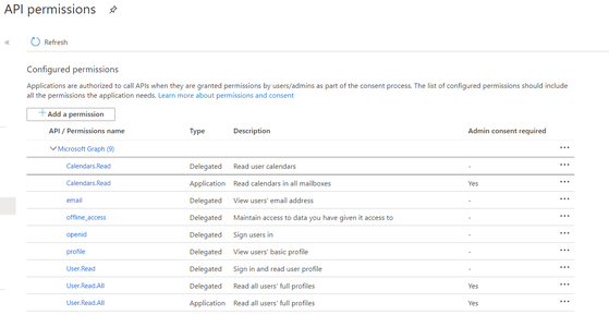
- Once your app is set up, you'll need to select the permissions needed. I asked for permissions related to profiles and calendars (see the image in the gallery for the full list of permissions). You'll need to select this same set. If you add more permissions, then you will need to change the scope appropriately in the next step.
Step 9: Modify and Upload AWS Code
This instructable assumes you are familiar with Node.js development and Lambda. Download the linked file, and make modifications to update:
- Microsoft App and Client information
- Google Key
- Email address for National Weather Service tracking
- S3 bucket name
- S3 folder name
- AWS Endpoint
You'll also need to download the following node libraries:
Once those changes are made, upload the code to the placeholder lambda you created earlier.
Step 10: Prepare Arduino IDE and Download Libraries
This guide also assumes you are familiar with Arduino. You will need to ensure your IDE is set up to work with an Adafruit ESP32. Follow the instructions here if you need assistance.
Once this is complete, download the following libraries:
- Adafruit_GFX (from the library manager)
- Adafruit_HX8357 (from the library manager)
- TFT_eSPI (from the library manager)
- TFT_eFEX (https://github.com/Bodmer/TFT_eFEX)
- PubSubClient (from the library manager)
- ArduinoJson (from the library manager)
- Adafruit_STMPE610 (from the library manager)
- Adafruit_MPR121 (from the library manager)
- Adafruit_INA219 (from the library manager)
- Adafruit_Sensor (from the library manager)
- Adafruit_BME680 (from the library manager)
- Tone32 (https://github.com/lbernstone/Tone)
Next we will need to modify a few of the libraries:
- Open the PubSubClient folder (in the Arduino/Library folder) and open "PubSubClient.h". Find the value for MQTT_MAX_PACKET_SIZE and change it to 2000.
- Next, open the TFT_eSPI folder, and open the "User_Setup_Select.h" file. Comment out any "includes users_setup..." lines and add this line:
#include < User_Setups/CUSTOM_TRICORDER_HX8357D.h>
Afterwards, download the linked Custom_Tricorder.zip file and extract the ".h" file to "TFT_eSPI/User_Setups" location in your Arduino libraries folder. I
Now, we can move onto updating the Arduino code
Step 11: Update & Install Arduino Code and Engage!
Arduino Code
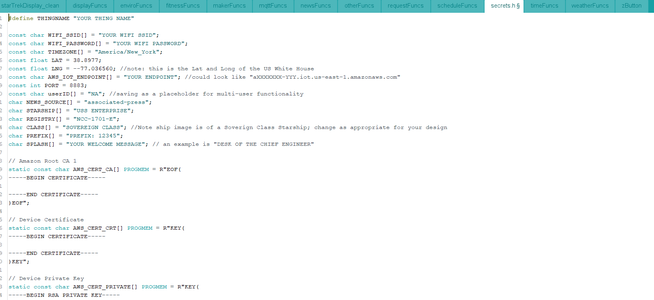
Download and unzip the linked file for the Arduino code. Go to the secrets.h tab. You'll need to update the following:
- WIFI_SSID = update with your wifi SSID
- WIFI_PASSWORD = update with your wifi password
- TIMEZONE = update with your timezone from this list
- LAT (you can use a service like "https://www.latlong.net" to find your Latitude and Longitude
- LNG
- AWS_IOT_ENDPOINT = you should have saved this from earlier. It should look like "dx68asda7sd.iot.us-east1-amazonaws.com"
- AWS_CERT_CA
- AWS_CERT_CRT
- AWS_CERT_PRIVATE
You will have also downloaded the certificates from an earlier step. Open then in notes editor (e.g. notepad) and paste the text between the 'R"EOF( ' and ')EOF";' . Be sure to include "-----BEGIN CERTIFICATE-----" or "-----BEGIN RSA PRIVATE KEY-----".
Image Files
The ESP32 comes with a small filesystem. We use this filesystem to save images for our program. You'll need to install the tool that allows you to upload files.
- First, visit the in depth tutorial on Random Nerd Tutorials.
- Once you have this working, you can upload the files in the data folder (also included in the zip file).
Engage!
Upload the final Arduino code, and you're done!
Note - The Star Trek name and Star Trek images are owned by CBS/Paramount. They have a fairly lax policy when it comes to cosplay and fan fiction - please read here if you have questions.

First Prize in the
Fandom Contest


