

Introduction: Matsuura Workholding Templates


In this lesson, you will learn the steps for setting up a CAM file in Fusion 360 for the Matsuura 5-axis mill. Then, you will learn how to prepare the inside of the machine for machining.
1) Open Fusion 360 and navigate to the CNC at Pier 9 Team Hub.
Here is an introduction to the Matsuura template file structure:
Recap:
--You may choose the Small (stock < 6"), Medium, or Large (stock < 13.5") Lang vise for rectangular stock.
--You may choose the 3-Jaw Chuck for cylindrical stock (1-7" diameter).
2) Bring your part into the correct template file using the steps in the video:
Note that this video focuses on cylindrical stock with the Lang 3-Jaw Chuck. For instruction relating to rectangular stock, additionally refer to the first DMS video in Lesson 3.
Recap:
--Navigate to the template file. Double click to open it.
--Drag part from Data Panel into active window.
--Move part until it's visible from all sides, then hit Enter.
3) Save the file under a new name using these steps:
Recap:
--Under File, choose Save As.
--Save in Master Folder under new name.
4) Create a joint between your stock and your part using these steps:
Recap:
--Use hotkey J to create a joint.
--For Component 1, click on the center bottom (or top) of your part.
--For Component 2, click on the center bottom (or top) of the stock.
--Flip joint around if necessary. Add an offset if you've joined the center top of the part and stock, to leave room for facing.
--Joint type should be Rigid. Click OK.
5) Edit the stock dimensions using the steps in this video:
Recap:
--In the Modify dropdown, choose Change Parameters.
--Under Favorites, change the stock dimensions and extrusion. Click OK.
Step 1: Matsuura CAM Setup
Now you're ready for CAM, Computer Aided Manufacturing.
1) Edit Setup 1 to verify the Work Coordinate System, Model body, and fixture:
Recap:
--Right click Setup 1.
--Verify that the Work Coordinate System is set to the center top of the receiver plate.
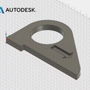
--Click Nothing next to Model. Then select the part. If you are having trouble selecting the model, expand the browser tree on the left and turn off the visibility of the stock (under Bodies).
--Click 8 Bodies next to Fixture. Verify that the Matsuura adapter plate, receiver plate, and vise with jaws are selected as the fixture.
2) Continue editing Setup 1 to verify the Stock and Post Process tabs:
Recap:
--In the Setup dialogue, click the Stock tab.
--Verify that the Stock Solid body is correct.
--Click the Post Process tab.
--Change the program number.
--Verify that the WCS Offset is 0.
--Click OK to create Setup 1.
Step 2: Matsuura Post Processing
You have now set up your template file.
1) Before starting CAM, confirm that you are using the latest Matsuura Mill tool library, labeled on the sticker outside the machine and available for download in the Pier 9 CNC Data Instructable.
The naming convention is: P9_matsuura_lib_MonthYear.hsmlib

2) Finish your CAM toolpaths, simulating as you go.
3) After you are done with CAM and all toolpaths are verified, cut your stock. Take measurements with a caliper and update your CAM Setups.
This is especially critical because you will be skipping the step of setting G54 by probing the back left corner of the stock (or wherever the WCS is set). If your stock dimensions are inaccurate, you could unintentionally put too much load on a tool.

4) When you are ready to post process, download the latest CAMplete post processor at cam.autodesk.com/posts.
Search for CAMplete APT.
5) To learn how to download and use CAMplete to simulate and post process your code, follow the steps in the CAMplete Instructable.
Contact the CNC team to receive the CAMPlete download link and network server name.
CAMplete is required for use of the Matsuura 5-axis mill. It provides a full simulation of toolpath motion, tool changes, approaches, retracts, and all other aspects of machine movement for more accurate collision detection. This is a critical step for five-axis machines with a small cutting envelope, because there are many more ways that the machine can crash compared to a standard 3-axis mill.
Step 3: From Software to Hardware
Now that you've simulated and posted your G-code in CAMplete, it's time to move into the CNC shop. The subsequent steps in this lesson take place at the Matsuura 5-axis Mill. You'll learn how to install Lang vises and chucks and verify the Work Coordinate System, G54.
Step 4: Installing a Lang Vise
If you are using a Makro Lang vise with rectangular stock, here are the steps for installing the vise and securing your stock.
1) Clean the receiver plate and vise with a dry cloth to remove chips and debris.
Any chips trapped between the two can damage the vise and receiver plate, and can cause tolerances to decrease over time.
If necessary, remove blue hole plugs by cupping your hand and using compressed air. For holes you will not need, replace blue hole plugs to prevent chips from getting inside the receiver.
2) Ensure the 8 mm allen bolt in the front of the receiver plate has been turned counterclockwise enough to allow the vise to sit flat on the plate.
3) Install vise by placing clamping studs in the bottom of the vise inside the holes in the receiver plate.
Ensure the front of the vise is facing you. The front jaw will have the letter L, indicating that the threaded rod that closes the jaws will tighten the jaws when turned clockwise. The front jaw will also indicate the maximum torque, 100 N m

4) Secure the vise to the receiver plate.
Use an 8 mm allen driver on the blue handled torque wrench set to 30 N m. Review Lesson 2 for a reminder on how to set torque levels.
Tighten until the wrench disengages with a clicking sound.

5) Install stock in vise.
Center the stock in the vise jaws with the tick marks along the jaws. If needed, use calipers.
Use the 12 mm socket on the black handled large torque wrench, set to 100 N m.
Tighten until the wrench disengages with a clicking sound.


Step 5: Using a 3-Jaw Chuck
If you are using cylindrical stock with the 3-jaw chuck, here are the steps for installing the chuck and securing your stock.
1) Clean the receiver plate and chuck with a dry cloth to remove chips and debris.
If necessary, remove blue hole plugs by cupping your hand and using compressed air. For holes you will not need, replace blue hole plugs to prevent chips from getting inside the receiver.
2) Ensure the 8 mm allen bolt in the front of the receiver plate has been turned counterclockwise enough to allow the chuck to sit flat on the plate.
3) Install chuck by placing clamping studs in the bottom of the chuck inside the holes in the receiver plate.
Ensure the front of the chuck is facing you. The 10.9 mm square socket should be slightly left of center.

4) Secure the chuck to the receiver plate.
Use an 8 mm allen driver on the blue handled torque wrench set to 30 N m. Review Lesson 2 for a reminder on how to set torque levels.
Tighten until the wrench disengages with a clicking sound.

5) Install stock in chuck.
Center the cylindrical stock in the chuck jaws and place in the "high" or "low" position.
Use a 10.9 mm square driver on the large black handled torque wrench set to 70 N m.
Tighten until the wrench disengages with a clicking sound.


Step 6: Verifying WCS G54
When you are ready to machine your part, follow page 12 in the Matsuura Quick Start Guide to verify the Work Coordinate System, G54.

Step 7: Additional Matsuura Resources
Congratulations on completing the Matsuura portion of the Workholding at Pier 9 course!
Here are some additional Matsuura resources. Note that we will provide links once they are available.
The Matsuura QuickStart Guide
A step-by-step guide for safe machine operation.
CAMplete Instructable
Required steps for all Matsuura users. How to download and install CAMplete, prepare your CAM model, simulate, and post process in CAMplete.


