

Introduction: Control a Motor Using Ultrasonic Distance Sensors (HC-SR04)
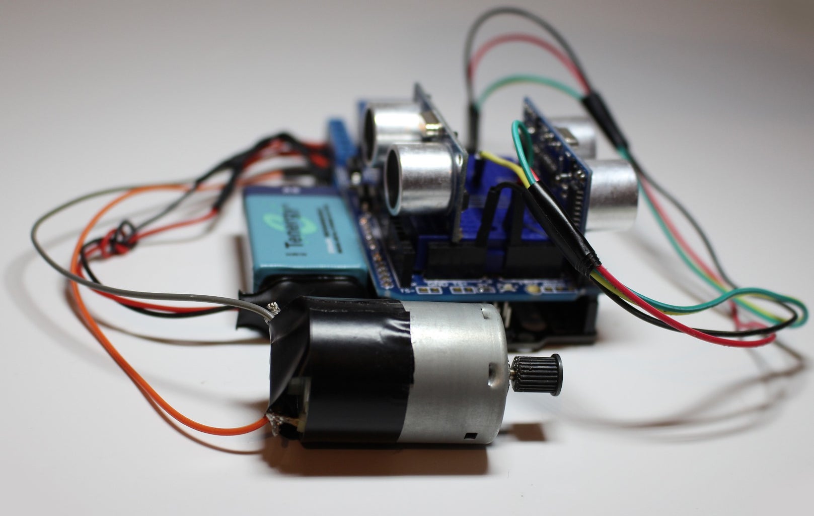


Hello everyone! In this project we will be controlling the direction of a motor using two ultrasonic ranging sensors.
If the right sensor is triggered, the motor will spin counter-clockwise.
If the left sensor is triggered, the motor will spin clockwise.
If both of the sensors or none of the sensors are triggered at the same time, the motor will not spin
This simple project is helpful if you want to build a car that is capable of avoiding obstacles.
The components that were used in this project are:
Everything from my last Instructable which includes:
Two 9v Battery
countless M-F jumper wires
A Motor
One 5v relay switch module
and...
Two Ultrasonic range sensor
One Breadboard or protoshield with breadboard
One SainSmart UNO or Leonardo
Youtube version of this project will be available soon in this channel:
Step 1: Wire the Breadboard + Ultrasonic Sensors


wire Connection for the Ultrasonic sensors:
Ultrasonic sensor 1&2 VCC -> arduino 5v
Ultrasonic sensor 1&2 GND -> arduino GND
Ultrasonic sensor 1 (US1 Right) TRIG -> arduino 12
Ultrasonic sensor 1 (US1 Right) ECHO -> arduino 11
Ultrasonic sensor 2 (US2 Left) TRIG -> arduino 9
Ultrasonic sensor 2 (US2 Left) ECHO -> arduino 10
I used staple clips instead of jumper wires for optimized cable management. This is completely optional and you can use jumper wires as an alternative.
Step 2: Connect the Relay Module + Motor


Wire connection for the Relay switches & motor
motor + or - -> relay1 comm pin
motor - or + -> relay2 comm pin
external power supply (9v) + -> Relay1 NO & Relay2 NO
external power supply (9v) - -> Relay1 NC & Relay2 NC
Relay module VCC -> arduino 5v
Relay module GND -> arduino GND
Relay module IN1 -> arduino pin# 7
Relay module IN2 -> arduino pin#13
This was covered in the previous Instructable where we connected the 9v battery to the DC motor. In this project, we will be using the left and right sensors to control the direction of the motor.
Unlike the previous Instructable, IN 1 is connected to digital pin#7 while IN 2 is still connected to digital pin#13
Step 3: Code!

Here is the link to the code.
Copy it and upload it to your board.
Don't forget to include the New pinglibrary. This allows you to communicate with multiple ultrasonic sensors easily.
//motor control:
//0 is LOW
//1 is HIGH
// motor spin (clockwise)
// digitalWrite(Relay1, 1);
// digitalWrite(Relay2, 0);
// motor spin (counter-clockwise)
// digitalWrite(Relay1, 0);
// digitalWrite(Relay2, 1);
// motor(off) //
digitalWrite(Relay1, 0);
// digitalWrite(Relay2, 0);
// motor (off)
// digitalWrite(Relay1, 1);
// digitalWrite(Relay2, 1);
Step 4: Done

If everything was done correctly, the rotation of the motor will be controlled by the objects that trigger the ultrasonic sensors.
As always, you can modify the code and change the voltage for your own projects.
If you want to see this project in action, please click on the link below:

Participated in the
Move It


