Node-RED: RS485 Raspberry Pi Tutorial

39K1317

Intro: Node-RED: RS485 Raspberry Pi Tutorial

The flow based visual programming tool Node-RED becomes more and more popular for Raspberry Pi developers. This instructable will show you how to use our isolated RS422 / RS485 Serial HAT under Node-Red for simple RS485 communication and for MODBUS applications too.

STEP 1: Tools and Materials

Materials:

Software:

  • Raspbian Stretch or Buster (with desktop and

    recommended software)

STEP 2: Free the UART in Raspbian Stretch or Buster

The easiest way is to use the raspi-config tool to switch the UART to the GPIO14/15 pins. take a fresh Raspbian image

  1. sudo raspi-config
  2. goto '5 Interfacing Options'
  3. goto 'P6 Serial'
  4. 'Would you like a login shell to be accessible over serial?' --> NO
  5. 'Would you like the serial port hardware to be enabled?' --> YES
  6. Finish raspi-config
  7. reboot the Raspberry Pi

Now you can access the UART via /dev/serial0

STEP 3: DIP Switch Setting for RS485 HAT

Our RS422/RS485 HAT comes with 3 DIP switch banks. You have to set these DIP switches for RS485 as shown in the picture above.

  • Switch 1: 1-OFF 2-ON 3-ON 4-OFF
  • Switch 2: 1-OFF 2-OFF 3-ON 4-ON
  • Switch 3: 1-OFF or ON* 2-OFF 3-OFF 4-OFF

*Depending of the position of the RS422/RS485 HAT in the Modbus line you have to switch the terminating resistor ON or OFF. Please switch the resistor to ON position only if the HAT is on one end of the bus line. In all other cases switch the terminating resistor OFF

STEP 4: Start Node-RED

Start Node-RED:

Node-RED is part of Raspbian Stretch and Buster (with desktop and recommended software). You can use the node-red command to run Node-RED in a terminal or on the desktop via the 'Programming' menu.


Open the editor:

Once Node-RED is running you can access the editor in a browser. If you are using the browser on the Pi desktop, you can open the address: http://localhost:1880.

STEP 5: Simple RS485 Communication

In this example flow the Raspberry Pi will send the text 'Hello World' via the RS485 after pressing the inject button. The flow will receive incoming strings (terminated by \d) and show the string in the debugging window on the right side.

The communication will be realised by using the serial in and out nodes, which are pre installed. It is very important to set the properties of the Serial Port to /dev/serial0 as in the picture above.

You can test the flow with a connected PC (via an USB to RS485 adaptor) and a simple terminal program.

STEP 6: MODBUS - Configuration 1

In the following steps I want to show you how to implement a simple Modbus RTU communication under Node-RED.

First we have to install additional Modbus nodes node-red-contrib-modbus via the palette manager or on the bash by entering:

npm install node-red-contrib-modbus

Now you can import the flow.

STEP 7: Modbus Configuration 2

After importing the flow we can take a look in the configuration of 'Modebus write' and 'Modbus read' nodes. It is imortant to set the 'Server' property to dev/serial0 and configure it as shown in the pictures above.

STEP 8: Modbus Test

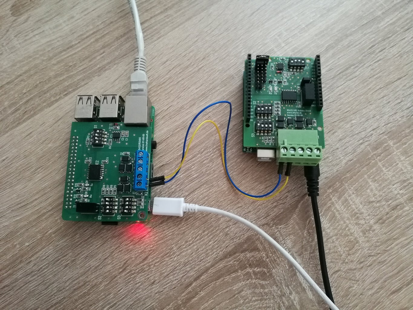
For the test I've connected an Arduino with RS485 Shield as Modbus slave (you can check this instructable for more information).

Modbus Read will poll Unit 1 all 2s and read 8 registers of the slave. You can see the result in the status of Modbus Response. Via the 2 injectors you can set the register 6 of the slave to 0 or 255.

12 Comments

it's not so simple like your description.
At the step 5 already, the system doesn't recognize the serial port, and node-red show in the log that permission is denied.
The process is not easy, could you revisit the procedure and upgrade (and more detailed) the post with the new version of raspbian?

Thanks
Hm, perhaps a problem with older versions of Node Red. (I've read something about such problems in the www).
I've tried today a brand new Node-Red installation under Bullseye - running on a Raspberry Pi4 without such problems. Every old example flow was running on the scratch....
Sorry, but I can not understand your problem. I've tested it today again
with the latest Raspberry Pi OS and a Raspberry Pi 4 and it works well
on the scretch. Please see my comment on the top too!
Hello I am trying to get the basic step to work and have tried using the simple program and have changed the Serial ports from the Serial0 to /dev/ttyS0 and probably most possible combinations and the serial Nodes say they are connected but I cannot send the message and get it to read out on the Debug window..
I have a USB Zigbee 3.0 dongle in a USB port and a SSD in another USB port then the Hat plugged on the top of the pins and have tried to get it to do the simple thing and it will not show message in debug window
".... the serial Nodes say they are connected but I cannot send the message and get it to read out on the Debug window...."

What is connected on the RS485 side? Notthing? In this case you will
not receive data in the debug window! For the basic example you have to
connect for example a RS485 USB adaptor and your PC as "other" RS485
device. With a terminal program you can send from the PC messages via
RS485 to the HAT and only in this case you will receive something in the
debug window.

I've updated flow1 in Step 5 today. With the dip switch setting
S1: ON-OFF-ON-OFF
S2: OFF-OFF-ON-ON

you can "see" on the UART the self sended messages by the HAT on the RS485 side and you will get the "Hello World" message in the debug window....
I can confirm that the shield is working as expected, at least with my python scripts.
Find here some read/write examples:
https://pastebin.com/u/rafi_chris

Unfortunately, the mentioned node red package raise errors. (FSM errors if multi IDs are used)
In my setup I'm using only one Getter and one Writer Node and I thought the state machine issues disappear with just one note. But, NO - It seems that for each slave address a new state machine is created.


Nevertheless, my setup is running stable.
All right... this Instructables is vague. It took a while, but I somehow managed to make it work.

I'm using two USB to RS-485 converters cross connected to each other in a configuration which I can make work correctly using a Python script I wrote. On the Raspberry Pi one of them becomes ttyUSB0 and the other becomes ttyUSB1. Settings are 19200, 8,N,1. When "deploying", both of these ttyUSBx ports are seen by Node Red.

Node-RED version: v1.3.3
Node.js version: v10.22.0
Linux 4.19.97-v7+ arm LE

== == ==

Just like torplatz noted in his message, I struggled to get past step #5

== == ==

Note that my own Python script can successfully transfer data from ttyUSB0 to ttyUSB1 (and vice-versa). Following the guidance in this Instructables did not deliver a payload to the "Debug Window" - It really should.. So after more "trying different things", I landed on a working set-up - I'm attaching images of my working system.

NOTE: I've added a "Bonjour" payload node for testing purposes.. just to confirm that some nodes can work. I also have a node for ttyAMA0 (the on-board UART) which also works when connecting those pins to a TTL to RS-485 Converter.

The TWO "blue" USB to RS-485 that become "ttyUSBx" which I used here are actually pretty nice, They have a Red LED that blinks on Transmit, and a Blue LED that blinks on Receive - very useful for troubleshooting purposes.

As for the TTL to RS-485 adapter, I used a low cost unit from eBay.

Sorry, but I can not understand your problem. I've tested it today again
with the latest Raspberry Pi OS, a Raspberry Pi 4 and our own HAT and it works well
on the scretch!

Please see my comment at the post of toreplatz too.

Some additional comments about your post:
1.) RS485 is a differtial serial interface. In dífference to a RS232 you have not to make a "cross-connection" between the wires for RS485 (half-duplex). "A" must be connected to "A" and "B" must be connected to "B" !!!!

2.) This instructable is written for our RS485 HAT. This HAT is using the on-board UART of the Raspberry Pi. Please note: You can use /dev/ttyAMA0 to send and receive data to the on-board UART, but the better and more modern term is /dev/serial0 as in the description.

3.) Simple TTL to RS485 converter from Ebay comes often without any auto transmitting feature. In this case you have to control the transmit/receive mode of such adaptors via an GPIO port.

4.) It is possible to test the function of the on-board uart (and of the USB ports with serial converters too) with a simple terminal program for example Minicom. No needs to write a Python script for this job. I've used for my tests Realterm on my PC connected via an simpe USB-RS485 converter to the RS485 HAT on the Raspberry Pi.

Hi Zihatec... Thanks for your response.. I just wanted to let you know that the Instructables that I commented on is able to work using "generic" eBay converters.. I had noted that in my original comments.. I think the real problem for me was the actual NodeRED. Even in spite of keeping my Raspberry Pi IOS (Raspian) up to date, I went ahead and did a " sudo apt-update" and a "sudo apt-upgrade". Then when I returned to NodeRED the options available to me were slightly different.. That is when it all started working. If you look at the images in my first post, you can see that I am using ttyUSB0 and ttyUSB1 (not trying to bounce the payload in both directions using the same port). But yes.. after overcoming some initial difficulties, updating my system, and confirming the functionality of my RS-485 adapters, I was able to make things work like in your Instructables using the generic eBay type RS-485 adapters.

From the begining I understood that your Instructables was geared to your own product, but Node-RED (as shown in your own images) does not specify your product, but standard "Linux" port names - in that sense it makes it very generic, and means that your Instructables should function correctly. No special configuration required.

On a side note.. I use (and like very much) Realterm as well it is a very versatile program. The industrial environment where I work, i use a large variety of RS-485 devices and interfaces.. On a daily basis we work on the design, build and test of control systems using RS-485 (RS_232 to a lesser extend).

P.S. - I also replied to one of your messages at the Instructables.
Some people reported to me that they have problems when both example flows are loaded in Node-Red at the same time, because /dev/serial0 is exclusive and only one flow can use this interface at the same time.
Hi Zihatec.. Thanks for your response.. Just note that I did make this work (up to step #5) with my own configuration.. My previous message includes photos of some of my hardware, and of the nodes I pulled together, but just know that it was a struggle to get there.. I always had HIGH confidence in my RS-485 set-up, because of my experience level with this hardware, and because I previously wrote a Python script that did an almost identical task and it worked perfectly (I can send that to you if you wish).. so I should not have had difficulties building two simple nodes and having them pass data. But, I did.. and it took time to resolve those. I'm not experienced enough to exactly why, but Probably like others, getting past Step #5 of your Instructable is not as "clean and easy" as shown. I'll again refer you to the images in my post, and just know that with the guidance of your Instructable, I was eventually able to make it work.
This is my problem at the step 7: modbus-client "sequential dequeue command not possible"
I bought the same card of the tutorial, but others operations needed to make it work.
Can you help me, please?