

Introduction: Pet Auto Feeder With Fusion 360


In this Instructable I would like to share with you how firstly I designed using Fusion 360 an Auto Feeder, which could be used for automatic feeding of fish or small pet etc.
The design uses some cool functions within Fusion 360 we will be using the Revolve tab to form the hopper and the sweep function to form the blades of the Screw Auger.
There is the main body which has provision for a 360 degree servo which is secured with 2 screws to the rear of the feeder, from this it drives a push on screw auger, which rotates within the cylinder delivering a measured amount of food, the main body also has the feed hopper which is designed with no angles ensuring a continuous flow of feed.
The Feeder will work best with the small pellets or something similar.
I like to try wherever possible to make the design as much a one piece print as it can be and think I have achieved that with this feeder, as such the Main Body, Feed Hopper and Servo mount is a one piece print with no supports needed.
The screw auger, lid for the feed hopper, end cap for the auger drive and also the clamping mechanism to clamp to clamp to a board or something these components are printed separately.
Supplies
Fusion 360
3D Printer
1.75 PLA
360 degree micro servo
CA Glue
Servo tester
Step 1: Designing the Fish Feeder With Fusion 360


After looking at some Youtube videos and giving the design some thought, I thought it would be best to go for the screw auger design with a food hopper, with some of the designs, getting the food into some of the little rotating compartments would be a bit of a challenge, and with the hopper design it's easy just to tip some pellets or flakes into it, and easier to rinse out as well.
So with a bit of an idea it was off to the drawing board so to speak, thinking how this would 3D print was my first priority so I started off with a 20mm centre circle, bearing in mind this could be any size you wanted big or smaller.
I then made a square around the circle, the flat surface will be better for 3D Printing
I extruded the square to 84mm and then using the bottom face, sketched a 14mm centre square and extruded the cut inboard, this would be where the food exits the feeder.
Flipping the design over, I created a centre circle approx 15mm where the hopper would be sat on top of the feeder and extruded this inwards with a cut.
The next task is to sketch the hopper, for this I am going to use the Revolve tool to form the feed hopper.
I needed to offset a plane to do this and using the back face of the body I brought this forward to where the centre of the 15mm circle is, we need to sketch a line vertically now and we use this plane to achieve this, I made this line 60mm this would be the height of the hopper.
I sketched a horizontal line from the bottom of the vertical line to the right, taking this just past the 15mm opening, the top vertical line would be half of what diameter the hopper is so it's 30mm then using the fit point spline tool I roughly sketched in a goblet shape and adjusted this with the pointers until happy with the shape, I then offset this line externally to 1.5mm what we are doing is making the wall of the hopper, there is a bit of adjusting to do with the ends of the offset line I had to snip one and join the ends, and join the top lines, giving us something to revolve, You highlight the area between the lines we have just created then click on Axis and then click on the vertical line for the axis and the hopper will be formed, join this to the main body, we can now move onto how to secure the Servo to the main body.
I forgot to take the screenshots for the Servo housing, I blame it on the heatwave we are having in the UK and it's fried my brain:)) but basically its just making a sketch to the dimensions of the Servo bearing in mind that the drive shaft on the Servo is offset by 16mm and then create tabs with 2mm holes to secure the Servo in place, I made a slot for the Servo cable and will make an end cap for this to tidy things up.
I changed the design of the hopper and drive end caps to what is in the screen shots, but they are just simple push on end caps, you can project the top edge of the hopper and offset by 0.3mm to create clearance for the cap.
For the clamping mechanism I wanted this to be adjustable so a simple 2 upright leg bracket which I will glue to the underside of the body, the rear leg will have a 5mm threaded hole and 5mm adjusting screw with an end cap so it will clamp to the tank, there is hardly anyway weight with the Feeder assembly.
There is only the screw auger left to design and for that we are using the Sweep tool.
Step 2: Designing the Feeder Screw Auger.


This was a bit of a head scratch for me at the time, how could I make it the correct diameter etc etc and the solution was to use the sweep tool in Fusion 360.
The Length of the Auger needed to be 84mm or so and the diameter needed to be just so, it needs to revolve freely in the cylinder.
My first attempts were with using the coil tool and it would probably have worked, but I opted for the sweep tool.
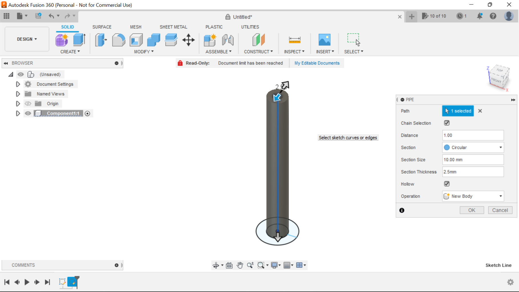
From the top plane I sketched a 10mm centre circle with a 5mm circle within this, I then created a 19mm circle around the whole thing, from the edge of the 10mm circle I sketched a horizontal line to the 19mm circle, finish sketch and create a new sketch selecting the front plane, sketch a vertical line of 84mm.
I extruded the 10mm circle up 84mm leaving the 5mm hole running through the Tube then selecting the sweep tool from the patch settings, the profile line is the horizontal line from the 10mm circle to the 19mm then selecting the path tab the path is the 84mm vertical line we created earlier, you may have to toggle the sketch on/off to see this, then you will see additional tabs appear, you set the degrees of the twist angle to whatever you want, you will see in the screen shot that I went for 2500, the last few tasks are to thicken the blade, so selecting the thicken tab, I made the blade 1mm and then using the combine tab combine both the blade and the centre tube.
I had issues printing the auger so I sketched a base to the bottom of it and extruded this to 2mm, this can be cut off later, this with a brim printed fine.
Step 3: Testing the Servo
To test the Servo and ensure it works ok with the screw auger I simply used a Servo Tester.
The Instructable is more of a how to with Fusion 360 but to be honest, there are simple Arduino Codes on the Internet that can do a timed feed drop for as many hours interval as you wanted, to delay the feeding, say every 8hrs.
If I did at some point add electrics, I would use the Arduino Nano and Servo Shield, Or even just a bare Nano, there only is one Servo after all, find a code, select the correct Data pin for the code on the Arduino and that's it.
Step 4: Assumptions

Another design I've enjoyed making, as I've often said designing something and then testing it is very satisfying.
The possibilities are endless, you could make it bigger, with a bigger Servo, use with an Arduino, maybe even voice control.
I hope you enjoyed this Instructable and thanks for looking.

Participated in the
Pets Challenge


