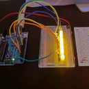
Introduction: Project 1 : LED Blink
Arduino is a unheard name for people who think electronics, technology and robotics is based on Lego Mindstorms. Actually Lego Mindstorms is only for experiencing and not for learning. It does not even have the basic robotics idea for learning. It's just like dragging pictures from the internet and into a document software.
Arduino is a cool techie item for robotics. It is programmed by Arduino Programming Software based on Java which makes beginners feel uneasy by listening the name Java. But its really cool and simple. There are also more micro controllers similar to Arduino like Rasberry Pi. Rasberry Pi is actually very much advanced. So beginners should better go for Arduino before heading out to other micro controllers.
The basic model or program for arduino is the Blink Project about which we will learn in this instructable.
Step 1: What You Require?
As mentioned before this is the most basic program that can ever be of Arduino. And if you are a beginner you need to be mentioned about the things you require.
- Arduino Uno or Arduino Mega 2560 (They are the beginning boards of Arduino)
- Jumper Wires (Male to Male)
- Led
- Breadboard
- 10 K (more preferable) or 1k resistor
- Cable (To connect board with your Computer for uploading the Program)
- Arduino Program (Downloadable from https://www.arduino.cc/en/Main/Software
Step 2: Build Your Circuit and Know Why Is It Designed So?
The above diagram shows 2 blue lines which represents the Jumper Wires. Jumper Wires are connective units. They transfer power and do a lot of jobs. In this program they are only transferring power. An Led requires 2 types of power to light it up. Positive and Negative. Positive Energy is supplied by Pin 13 which is distinct than the other Pin giving Positive Energy by its name. It's vice versa for identifying the source of power and where is it transferred. An led when directly supplied by positive energy fuses up that's why we use a resistor. Before me move forward let's discuss about the positive negative rods of the led. The longer is positive and the shorter is negative. The resistor is connected with the positive rod which goes in the same row. In the same column but different row of the other end of the resistor comes the jumper wire connecting it with Pin 13.
Negative energy is noted as GND and is directly supplied to the shorter rod of the Led using a Jumper Wire. That completes the circuit diagram and why is it placed or designed in this way.
Step 3: Now for the Software and Understanding It
The software is powered by Arduino Programming.
void setup() {
pinMode (13, OUTPUT); }
void loop() {
digitalWrite (13, HIGH);
delay (1000); digitalWrite (13, LOW);
delay (1000);}
The Void Setup is an automatically appearing part of the Program that is for setting up the parts of the Circuit which are needed to be distinguished like Pin for positive energy supply of the Led's. Most beginning programs use pinMode to set the pin and its function. Here the pin is 13 and its function is to give which is said by the word Output. Void Loop Is the real program which repeats itself infinitely. digitalWrite is used for telling the use of the prescribed item like for example here pin 13 is supposed to be on which is showed by HIGH. LOW is for off. Delay is for pausing or continuing for upto until this time. 1000 for delay function is equal to 1 second.
Thanks a lot for all the support and do not forget to share and follow.

Participated in the
First Time Authors Contest 2016


