

Introduction: Time Slider


A digital clock using sliding grids to show or hide the segments of the digits.
Each minute the sliders move in a synchronized manner to show the current time.
The clock is powered by an Arduino Mega and it uses a DS3231 RTC to keep the time. Each digit has two sliding grids which are affected by small stepper motors.
I designed it with Autodesk Fusion 360 and 3D printed it on a Prusa MK3S.
Step 1: Parts List


- Arduino Mega
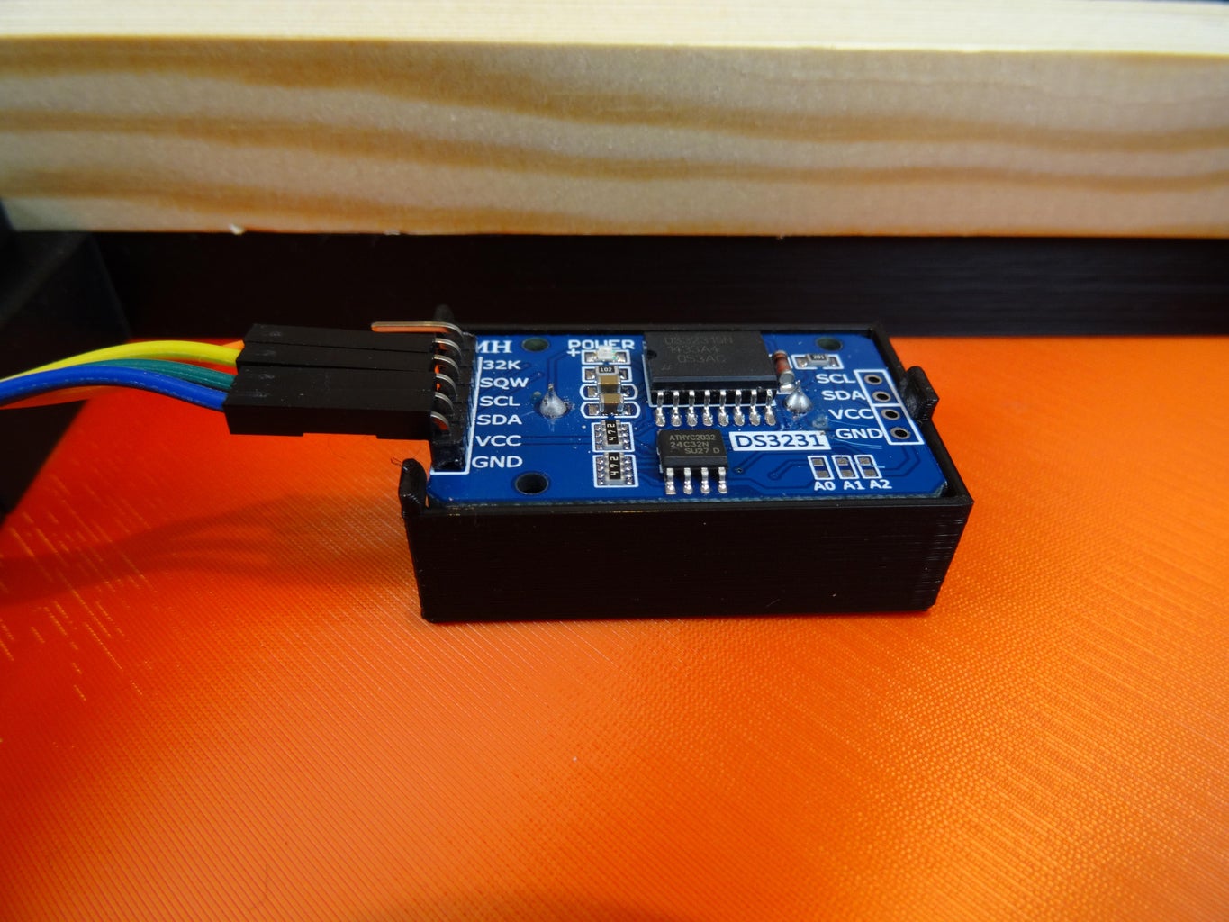
- DS3231 Real Time Clock Module
- Eight stepper motors 28BYJ-48 with ULN2003 Driver
- 82 cm Wooden strip 19x19mm
- Steel Wire 1m
- 46 Washer head screw 4.2 x 14 mm
- 16 Button head screw and nut M4 x 10
- 18 self tapping screws M3 x 5
- Dupont Wires
- 5V power cable with DC plug 5.5x2.1mm
- Power supply 5V/2A
- Power supply for the Arduino Mega
Step 2: 3D Printed Parts
3d Printed Parts:
- One A1 - A8
- Three B1 and B2
- Two C1
- Four Digit
- Two Dot
- Four Grid
- Eight Gear
- Four L1 - L4
- Four R1 - R3
- Twenty Rackjoin
- Twenty-eight Thinjoin
- One ArduinoMount
- One DS3231Mount
- Two ULN2003Mount
I printed it in PLA. Layer height: 0.2mm, Infill 15%
I used Brim on parts A, L and R to avoid warping.
I used approximatey 2kg black, and 350g red PLA.
Attachments


Step 3: Electronic Schematics

Step 4: Assembly


- Attach the plates B1 and B2 on the body A1 - A8. Use Washer head screws.
- Attach C1 onto A1+A5 and A4+A8. Use Washer head screws.
- Install the wooden strip with Washer head screws.
- Fasten the steel wire to the wooden strip with Washer head screws. Adjust the length of the steel wire so that the clock hangs flat to the wall and does not tilt outwards.
- Glue Digit, Dot and Grid.
- Assemble L1-L4. Apply some glue to the L-pieces and attach the Rackjoin. Make sure it alligns with the rack.
- Glue on Thinjoin. Make sure the rack is perfectly straight so it will slide well in the tracks.
- Repeat above steps with R1-R3.
- Test the sliders in the tracks. Make sure they slides well. If not, fix it by sanding it. And maybe lubricate with silicone spray.
- Attach the stepper motors with M4 screws.
- Attach the gears.
- Glue Arduinomount. It is higher on one side - the Arduino Mega is mounted tilted so that the usb connector will be accessible. Place the lowest side towards the center of the clock.
- Glue ULN2003Mount and DS3231Mount.
- Mount the Arduino Mega and the ULN2003 drivers with small M3 screws.
- Attach DS3231 (snap fit).
- Connect the wires from the motors to the ULN2003 drivers.
- Connect Dupont cables between the ULN2003 drivers and the Arduino Mega as defined in the source code.
- Make a harness connector, connecting all the + pins on the ULN2003 drivers to the positive DC connector power cable. GND on the Arduino Mega and all the - pins on the ULN2003 drivers to the negative DC connector power cable.
- Connect DS3231 SDA, SCL, 5V and GND to SDA, SCL, 5V and GND on the Arduino Mega.
Step 5: Software
Arduino libraries:
If you want a 12 hour display (why would anyone want that on a digital clock) set the variable twelve_hour_mode to true
Attachments

Step 6: Operation

- Slide the grids into the tracks so that the gears engage.
- Turn on the power.
- Enjoy the show.

Judges Prize in the
Clocks Contest


