

Introduction: Ultrasonic Eyes


I wanted to make a quirky project using some 8x8 matrix LEDs and some ultrasonic sensors... something different from what other people usually make with ultrasonics - and I wanted it to be fun and playful.
So I created what I call UltrasonicEyes - a fun project that you sit somewhere near where people move around and it will look around at where people are, and blink and well, just weird you out in a fun and creepy way!
Lets go through how to make one!
Step 1: What Do We Need?
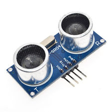
Ultrasonic sensor modules are designed to detect obstacles and to determine how far away the obstacle is, so they generally have a detection distance of up to 3-4 meters, which is a good distance for this project to be placed inside a living room or office area.
I am using 2x HC-SR04 modules I picked up from e-Bay. You can find them super-cheap.
The modules are pretty straightforward to use, and only require 3 or 4 wires, to connect to an Arduino micro-controller.
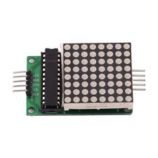
The 8x8 led Matrix modules I chose to use allow chaining, so only one of them needs to be connected to the Arduino, and the second module connects to the first.
The modules use SPI, so we only require 5 wires to go to the Arduino to control eye images on both displays. We need two of them of course!
NOTE: The code provided uses Hardware SPI, so if you are using a different Arduino board than the Nano, please check which of the pins are Hardware SPI pins for MOSI and SCK and wire them up accordingly!
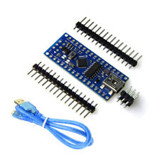
You'll also need an Arduino compatible micro-controller of some type. I am using a Nano (compatible) because it's small enough to fit in the case, has USB for power/programming the firmware and it has a stack of GPIO's to connect everything too.
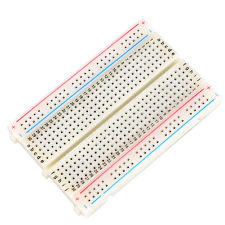
I have soldered everything onto a proto-board that is the same size as a half breadboard, but I'd recommend you just build everything onto a half sized breadboard first, as that way the project requires no soldering and can be easily pulled apart or changed.
The last few things you'll need are an LDR (Photo resistor) for detecting light, a 330ohm resistor and a bunch of breadboard wires, both male to female, and female to female.
NOTE: You can use any color wires in this project... there is no requirement to use the same colors that I specify, but, it's always good practice to use red and black for POWER and GND, and use other colours for other wiring as it makes it super easy to identify which wires have power running through them and which wires are being used for data & signals.
Step 2: Putting It All Together
Lets start by plugging the Nano onto the breadboard right at the end so the USB is hanging off the edge, but still keeping all pins plugged into the board.
POWER and GND connections
Now connect a black wire from the GND connection on the Nano to the GND rail on the breadboard. Now do the same with a red wire, connecting the 3V (or 5V if that is all you have) to the POWER rail on the breadboard.
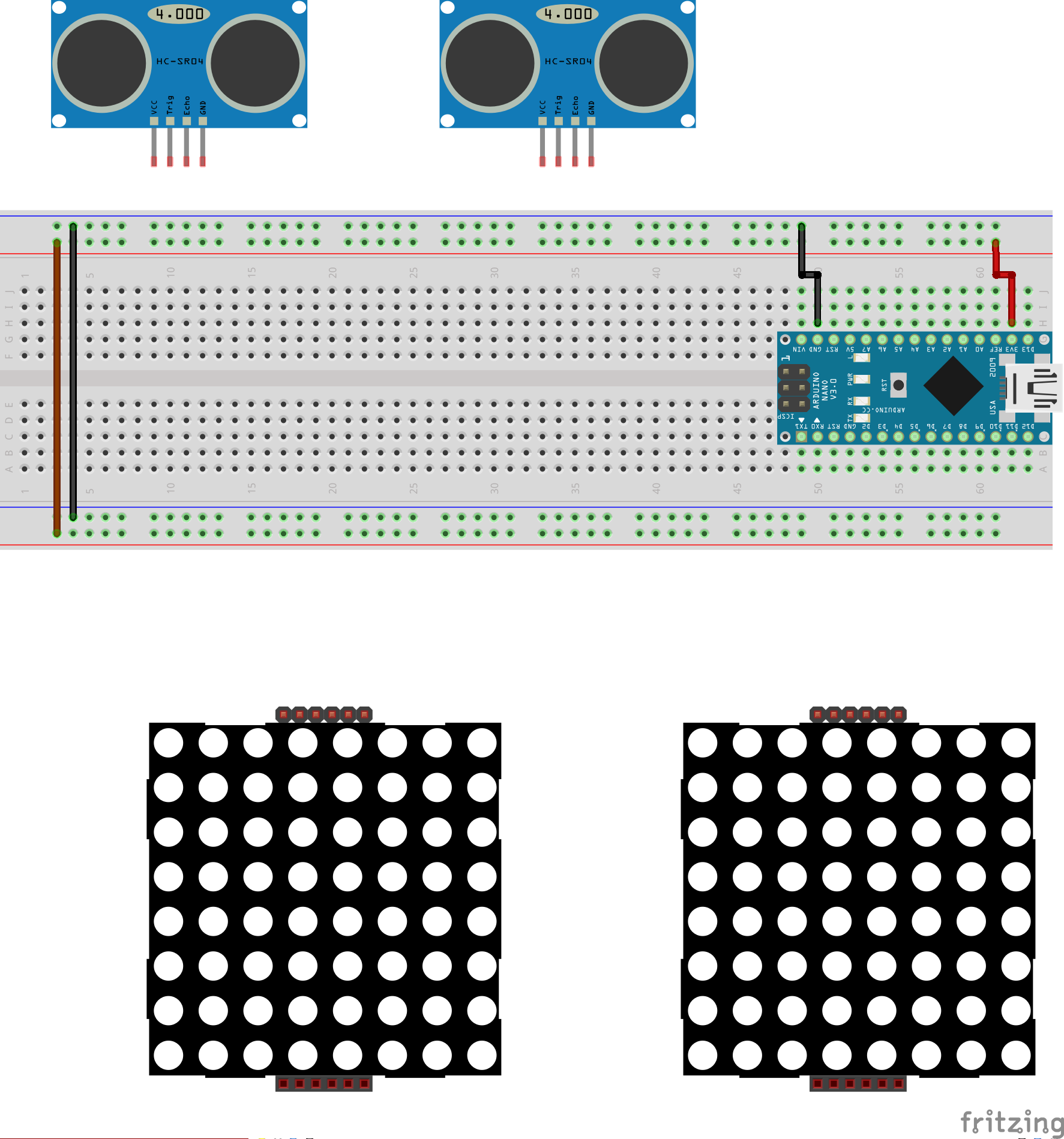
While we are working on the GND and POWER, lets connect a black wire between the two GND rails on each side of the breadboard. Do the same with a red wire and the two POWER rails.
Lets wire up the Ultrasonic sensors
Connect a black wire between the GND pins on each of the Ultrasonic sensors to the GND rail on the breadboard. Do the same with a red wire and the VCC (POWER) pins on the sensors and the POWER rail on the breadboard.
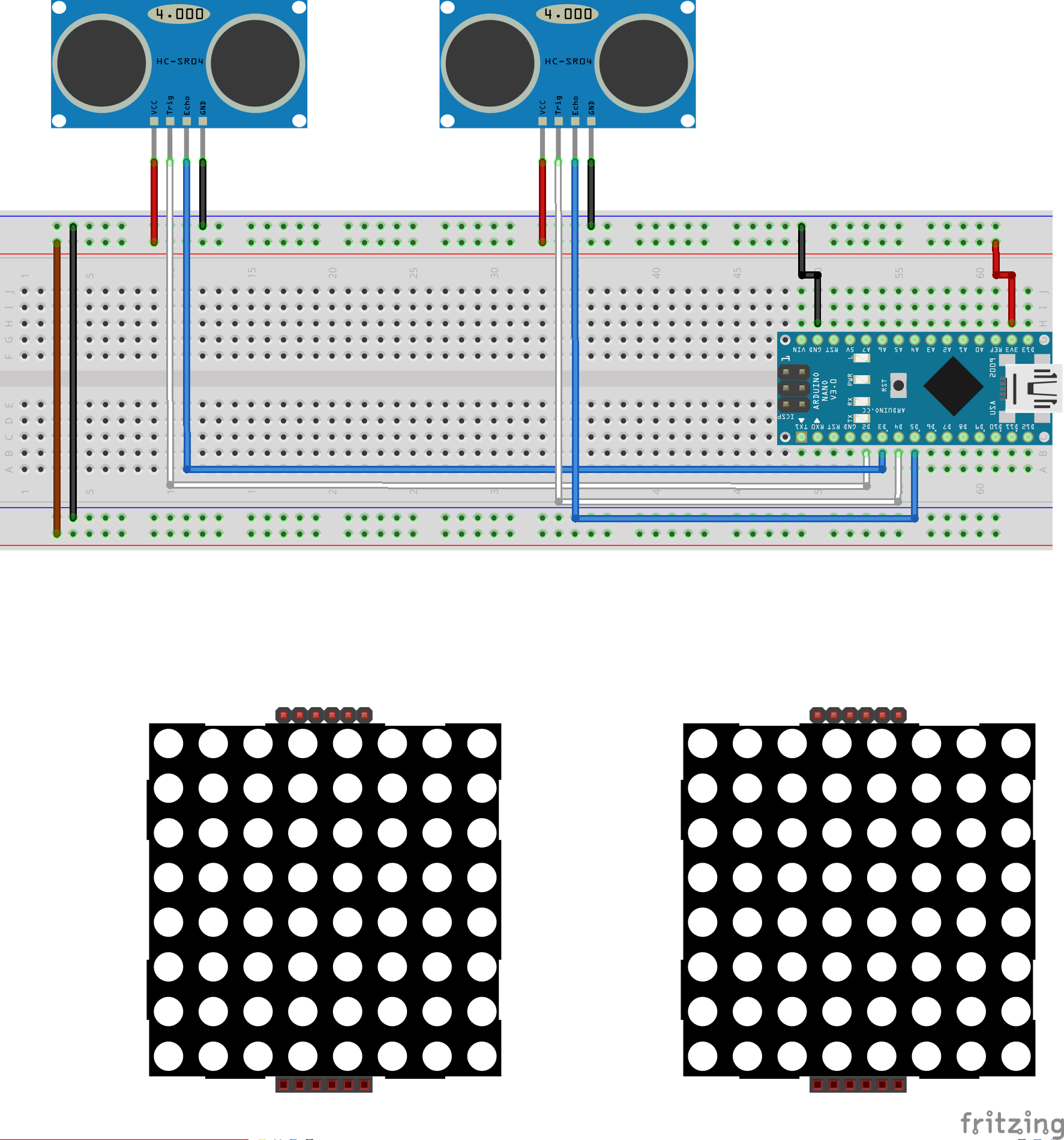
Now lets hook up the following white and blue wires:
- White wire from the TRIG pin on sensor 1 to Digital pin 2 on the Arduino
- Blue wire from the ECHO pin on sensor 1 to Digital pin 3 on the Arduino
- White wire from the TRIG pin on sensor 2 to Digital pin 4 on the Arduino
- Blue wire from the ECHO pin on sensor 2 to Digital pin 5 on the Arduino
Great job! That's the Ultrasonic sensors taken care of!
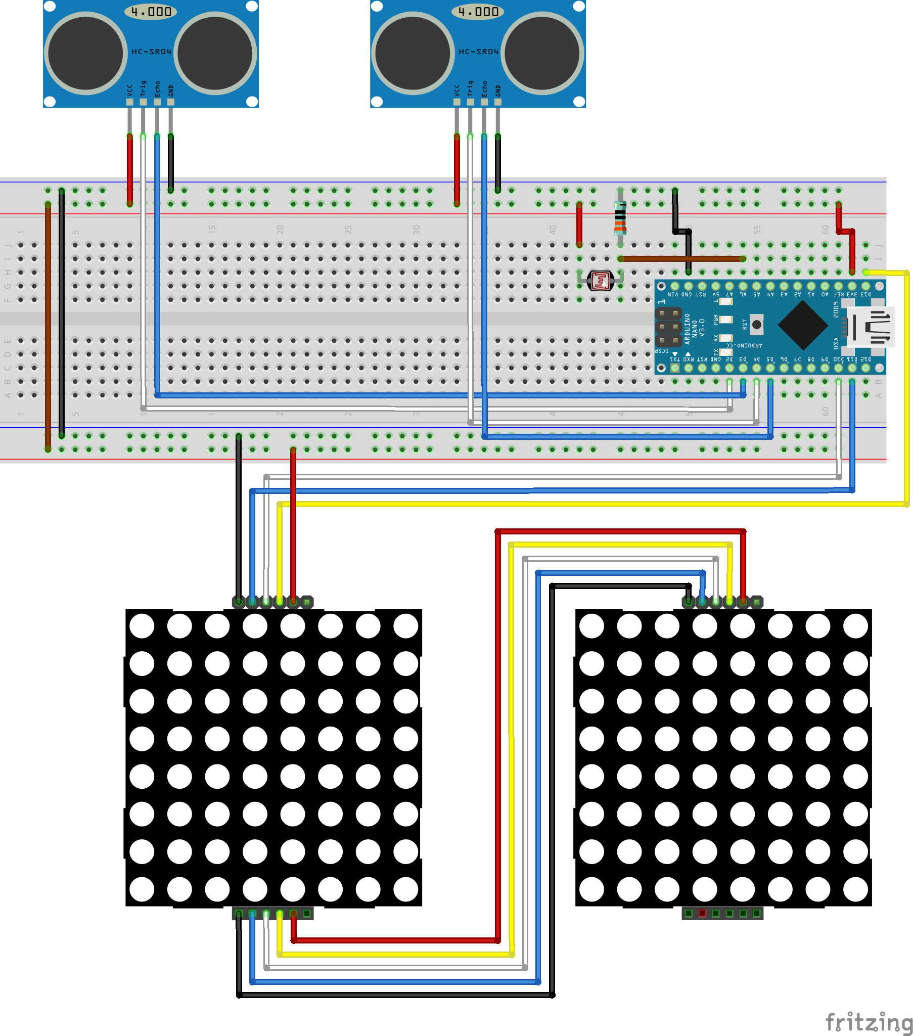
Connecting the two 8x8 LED matrix displays
Connect a black wire between the incoming GND pin on one of the LED matrix displays to the GND rail on the breadboard. Do the same with a red wire and the incoming VCC (POWER) pin on the display and the POWER rail on the breadboard.

Connect a black wire between the outgoing GND pin of display one and the incoming GND pin on display two. Do the same with a red wire and the outgoing VCC pin on display one and the incoming VCC pin on display 2.
While we are connecting wires between the 2 displays, lets finish that part off...
- Connect a yellow wire between the outgoing SCK (Clock) pin on display one and the incoming SCK pin on display two.
- Connect a blue wire between the outgoing MOSI (Data) pin on display one and the incoming MOSI pin on display two.
- Connect a white wire between the outgoing CS (Select) pin on display one and the incoming CS pin on display two.
Great! Now lets connect the rest of display one to the breadboard...
- Connect a yellow wire between the incoming SCK pin on display one and digital pin 13 on the Arduino.
- Connect a blue wire between the incoming MOSI pin on display one and digital pin 11 on the Arduino.
- Connect a white wire between the incoming CS pin on display one and digital pin 10 on the Arduino.
REMEMBER: The code provided uses Hardware SPI, so if you are using a different Arduino board than the Nano, please check which of the pins are Hardware SPI pins for MOSI and SCK and wire them up accordingly!
Well done. Now on to the final wiring steps...
Connecting the LDR and Resistor to detect ambient light
Before we connect these wires, why are we even doing this step? Well, I am glad you asked! The LDR connected to the Arduino will allow us to detect wether it is light or dark around UltrasonicEyes and we are going to use that information to brighten or dim the LED displays accordingly.
We don't want the displays super bright at nighttime as in darker light, we can still see the displays quite well when the brightness is around 30%, but in daylight, or in a bright room, we need to punch the brightness higher to make the displays more visible.
Ok, lets get this last step complete so we can move on to putting it in the 3D case!
Connect the LDR across 2 rows of pins on the breadboard, just like in the wiring diagram above. Leave room to place the resistor and a wire that will go to the Arduino.
Connect the 330ohm resistor between one row of pins on one side of the LDR and the GND rail of the breadboard.
Connect a red wire between the row of pins on the other side of the LDR to the POWER rail of the breadboard.
Finally, lets connect a brown wire between the row of pins that the 300ohm resistor is connected to and Analogue pin 4 (A4) on the Arduino. It needs to be an analogue pin because we need to read a value between 0 and 255 from the LDR (light strength) instead of just 0 and 1, like we would get from a digital pin.
Step 3: Lets Power It Up and Upload the Code
Ok, that's it, we are all wired up. Time to plug the USB cable in between the Arduino and your computer, and upload the UltrasonicEyes sketch provided below in the to see it all working.
Once it's powered up and the code has been uploaded, walk around in front of your sensors, or move your hands in front of them and see what happens!
Want to make it more permanent?
Looking to make your UltrasonicEyes more permanent? Check out my video that covers taking the breadboard version and soldering it to a proto-board here...
And then print the 2 parts of the case on any 3D printer and assemble like I did in the video!
I'm also looking at expanding UltrasonicEyes to have a capacitive touch button (or regular button) to cycle through different eye shapes!
You can check out the rest of my projects & videos at... unexpectedmaker.com
Follow me on twitter, Facebook and Instagram
That's it!


