

Introduction: 2M Yagi Antenna


This antenna is my 'experimental' twist on the tape measure yagi antenna. I, like many readers, have built numerous 'tape measure' style antennae for the odd field day or DF event and whilst they do the job admirably I have a few issues with them; Firstly they are ugly and secondly they don’t seem to hold up well after some daily abuse. Now I’m sure both points are not really issues to anyone except me but I’m sure that if you are reading this you have looked longingly at the beautiful & professionally built antennae that are sold for frankly more than I’d like to spend.
The experiments in play here are the construction technique / materials and the offset feed point. Initially in my research I found the common feed point technique such as inline or gamma match offered itself to a less than suitable structural problem in that the driven element of the antenna was spit into a dipole at the middle and as such each arm would be left with less of the boom material to anchor itself, now I am aware that there are some fantastic designs available to conquer this but at the time there required tools, skills or parts better than I had available.
Step 1: Materials & Tools
When it come to building this antenna I made the following requirements:
- Must be cheap to make
- Must be easy to assemble (possibly by children)
- Must fit into my tiny car
- Must not need special or heavy tools
Most of the parts can be purchased at a local DIY store, however the main component of the build are Nylon Shoulder Washers which I have only found to be available online.
Materials:
4x 1M M4 Stainless Steel threaded rod*
1x 1M 10mm2 Box Aluminium
8x M4 3mm Nylon Shoulder Washers
10x M4 Nuts (Stainless Steel)
Consumables:
- Various crimps
- Cable Ties
- Coax (RG58 or better)
*The reflector needs to be 1.05M in length, take a tape measure to the DIY store as there is some tolerance in the actual provided lengths. I got lucky and found one that was 1.06M. If unlucky see my modifications section
Step 2: Design

Element Lengths
- Director: 890mm
- Driven (total): 940-960mm
- Reflector: 1005mm
The antenna is constructed from M4 stainless steel threaded rods, as they are relatively inexpensive and common place at most DIY stores. Additionally, it is an easy material to work with and does not require any special tooling. The boom is constructed it from 10mm2 aluminium box section, again it’s cheap and stocked in most DIY stores. The feed point is fed directly with coax and the small common mode balun consists of just a few turns around the boom held in place with cable ties. Insulation between the elements and boom is maintained using Nylon Shoulder Washers.
Offset Feedpoint
What makes this antenna so strong is it's unusual feedpoint, it is offset so that each element passes through the box section providing a very secure fitting. I originally came across the design in an 1998/1999 article from the ARRL called the 7 in 7.
Each arm of the driven element is offset and as such acts as both the feed point and a matcher! The feed gap in a dipole directly influences the impedance and radiation pattern, so in this design we are effectively offsetting the antenna and altering its electrical length. Further research turned up little information on this design so I decided to build it and test it myself. I took the original dimensions and (after some trial and error) modified them slightly to suit the materials I was using, threaded rod. As radio frequency energy ultilises the 'skin effect' the ridges from the threadeding actually contribute towards the overall electrical length, which is great for the antenna as it reduces the amount of material required.
Step 3: Construction


Draw a centre line down the box section (5mm) and then proceed to mark out and centre punch the locations for the elements (pictured above). At the points marked drill though both walls of the box steel and clean up the holes of any swarf or sharp occlusions, ideally use a drill press and suitable vice to ensure that all holes on both sides of the boom line up evenly. Insert the nylon grommets into the holes and check alignment. Measure, mark and cut the director & reflector elements, be careful when handling the cut pieces as the ends can be sharp.
Measure and cut the remaining rods into get two 550mm lengths. Mark a centreline onto the reflector and director rods, then made a further two marks at 5mm on both sides of the centre, this is where it will align with the boom. Proceed to thread the rods into their locations on the boom and enjoy threading on the nuts to secure both elements in place (Whilst I am unable to recommend it for safety reasons, I used a cordless drill to speed up this process). Once both rods are in place you should dull the ends using sandpaper to prevent injuries.
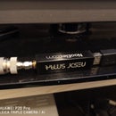
Thread a suitable crimp connector along with a nut on both sides (like a sandwich, picture below) onto one of the driven rods, thread to at least 25mm along the length. Place the rod into position and secure with a nut on the long end. Repeat this again for the remaining driven rod to form a dipole.
Finally solder and secure the coax to the crimp connectors, insulating as appropriate and form the balun of 4-8 turns of coax if required using cable ties. Using sandpaper make sure to dull the ends of all elements, Personally I'd go one step further and dip them with ‘rubber-in-a-can’ to make it safer.
Step 4: Calibration
Tuning the antenna should be done with a capable antenna analyser but you can may use my dimensions if unavailable* (at your own risk). The feed point impedance should be as close to 50ohm’s as possible. I managed to find a sweet spot of 51Ohm presenting an SWR of 1.1:1 at 145Mhz with minimal effort, I advise making sure there are no metallic objects in proximity of the antenna during calibration. Adjust the driven elements equally until a suitable match is found by threading the rods to change their lengths in equal proportions. Upon calibration you may trim the unused rod down to approximately 10mm from the nut and dull the ends. I suggest using locktight or a suitable glue to secure the nuts into position.
* It is possible to use a suitable SWR meter to adjust the antenna for best match, make a QSO with a friend and jump around the band to make multiple points of calibration.
Step 5: Modifications and Improvements

The design and construction of this antenna is open to many modifications,and even other designs (TDOA antenna maybe). If you were unable to find a slightly longer length of rod for the reflector you can try using something like these M4 brass couplers to extend the length of the reflector (or all elements), this would additionally provide further tuning capability to the antenna. Mounting of the antenna is up to the end user, there is enough length behind the reflector to utilise for mounting or the attaching a handle. For my prototype I constructed and shaped a basic handle from pine construction timber (cheap!). I see no reason why the construction technique could not be scaled up to M6, M8 or even M10 rods with a suitable supporting boom size for other bands.
I have had some more ideas for this design, but please let me know what you come up with!
Scale it up!More ElementsParasitic Elements for other bandsBuild a tripodDrill out boom to reduce weightUse better coax

Participated in the
Remix Contest


