

Introduction: 3D Print En Plein Air


Mix 3D printing, plein air painting, site-specific art, and instruction-based art together and this is what you get--a portable system that lets you generate 3D models from the environment and print those models by following the commands typically given to 3D printers. Essentially, you 3D print by hand with whatever materials you deem necessary. This project represents a step along an ongoing project I call Being the Machine (website, instructable, publication). The project explores ways that we can get out of the lab, engage our senses, and combine digital manufacturing workflows with the vibrance and unpredictability of the physical world.
Step 1: Overview


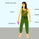
The system consists of electronics, a laser guide, a mobile app, and materials, all encased within a portable easel that allow you to build with data in the wild.
The backbone of the system is the mobile app. This app generates 3D models from images taken in your building environment and communicates with the hardware that guides the building process. Use the app to capture an image and generate a model, then, you can begin to build that model by hand.
Building is as simple as following the movements of the laser pointer, almost like a game of connect the dots. The laser guide mounted at the top of the box projects a single point onto the building platform. This is your starting point. Place some materials on that point and use the remote control/key fob to advance laser guide to the next point. Once the point has moved, you follow it with your materials. Point by point, layer by layer, you follow the laser point with your materials until the model is complete. As you build, the mobile app gives you live updates as to where you are in the building process.
Step 2: Modify the Easel

Easel Modification Materials:
- US Art Supply Coronado French Style Easel & Sketchbox with 12" Drawer, Wooden Pallete & Shoulder Strap
- 1/4" Birch (or other) Plywood
- 1/8" Birch (or other) Plywood
- 8" x 10" Canvas Boards
- Laser Cutter
Step 3: Modify the Easel: Disassemble Original Easel


- Remove the part of the easel that is intended to support the canvas, outlined in green above. This is as simple as unscrewing the hardware.
- Take the palette out, set it aside to use in another project.
- Place the drawer of the easel into the laser cutter, with the bottom of the drawer facing up. Use the attached PDF to cut a hole in the longest and skinniest draw partition, as close to the outer edge as possible. This hole will allow the laser mount to sit inside the easel. Once you cut the hole, sand down the edges to ensure a tight fit between the arm mount (to be assembled later) and the drawer.
- Optional: Use a screwdriver to unscrew the lid. Place the entire lid in the laser cutter and create a circular, square, or hexagonal (whatever you like) window so that you can see the world while you fabricate. Once cut, screw the lid back on.
Attachments

Step 4: Modify the Easel: Assemble the Building Platform


- use the 1/8" plywood and cut the attached PDF. This file creates two nearly identical cuts, one for the base of the palette and the other for the top with cut outs for the canvases to be placed in.
- Use wood glue to attach the two sheets together such that the final form looks like a normal painting palette with a shallow 1/8" deep rectangular hole in the center.
- Sand the outer edges of the palette until it forms a nice snug fit into the drawer of the easel.
- Place 2 of the 8" x 10" canvas boards in the opening of the palette.
Attachments

Step 5: Modify the Easel: Assemble the Electronics Housing

- Use your 1/4" plywood and cut the attached PDF on the laser cutter
- the pdf attached has two layers: the red marks are the cutting lines. The layer with green and blue labels is intended to help with assembly, they do not need to be cut.
Attachments
Step 6: Modify the Easel: Assemble the Laser Guide Housing


- Laser cut the attached PDF file on 1/4" playwood.
- Assemble the pieces according to the image.
- the pieces labeled "c" should be glued to the inner face of the lid on either side of the lid clamp. Make sure to align the top edge of the block with the lower part of the clamp. Otherwise, the lid won't close.
Attachments
Step 7: Assemble the Electronics


Parts:
- 5V Arduino Pro Mini
- 2400 mAH, 3.7V Lithium Polymer Battery
- Adafruit PowerBoost 1000
- 4 Button Radio Receiver
- 4 Button RF Remote
- SparkFun Blue SMiRF Silver
- Rocker Switch
- Laser Diode
- 2 x HiTech HS-55 Servo
Accessories:
- FTDI Basic Breakout (for programming the Pro Mini)
- USB Mini Cable (for connecting to the FTDI Breakout)
- USB Micro Cable (for connecting and charging the LiPo
- Perf Board (for hard wiring the electronics inside the lid)
Process:
Refer the attached wiring diagram for assembly instructions. You're wiring may vary based on the electronics you use. This set up fits within the tight space of the lid. It should also be noted that I cut off one of the power rails of the perf board in order to conserve space. I also used multi connector stranded wire to make the connection between the electronics housing and the laser housing.
Attachments
Step 8: Assemble the Laser Guide


Parts:
- 2 HiTec HS-55 Servo motors
- 1 Laser Diode
- 1/4" 20 Hex Nut
- Custom 3D Printed Pan Tilt Bracket
- you could also try using any other pre-fab servo driven pan tilt bracket but you'll have to hack a few things
- 4 Screws (to attach servos to bracket)
- 4 Hex Nuts (to attach servos to bracket)
Process:
- Press the 1/4 20" hex nut into the base of the laser mount
- Press the smaller hex nuts into slots of the arm of the laser mount
- Place each servo into its corresponding position on the arm and screw them into the hex nuts you previously inserted.
- Use a screw driver to take the "x" shaped servo horns off of the servos. Set the horns aside and be sure to hold on to the screws. Hook each of your servos up to a program that sets them to their center position (1500 microseconds).
- Using one of the screws that previously held the servo horn, screw one of the servo heads into the base.
- Using the the other screw from the servo horn, screw the laser diode holder onto the other servo head. When assembled and sitting on a table, the laser point should point parallel to the table in a direction that passes directly over the hex nut in the base.
Step 9: Mount the Laser Guide Inside the Housing


Parts:
- 1/2" long 1/4"-20 bolt
Process:
- Hold the laser guide in one hand with the base pressed against the board and oriented so the laser points straight up. Slip the bolt through the hole and twist until the base holds its position tightly. The direction of the laser pointer does not have to be perfect, as you can modify the laser's "center" position in code during a later step.
Step 10: Upload the Arduino Code, Fine Tune a Few Things

Code:
Process:
- You want to do a bit of fine tuning in the code to make sure that you're laser is pointed at the center of the canvas closest to the lid when the code starts running.
- Manually update the value of ctr_x and ctr_y in the code until your laser point hits the center of the canvas. It doesn't have to be perfect, as you can see in the photo that mine is slightly off, but it should be somewhere close.
Step 11: Install the App
Code:
Process:
I created the mobile application using Cordova, a platform that lets you code in javascript and port that code to various phone platforms. So far, I have only tested the code on my personal Android device. Different phones have different equipment so you will have to make sure that the BlueSMiRF module I use in hardware is compatible with your phones Bluetooth (I'm fairly certain newer iPhones use BlueTooth Low Energy, which uses a different hardware module). Additionally, The code allows for 2D and 3D previews of the models that it generates. However, the "webview" on older Android phones like mine does not support webGL, so, there is no simple way to preview the 3D model on some devices.
If you want to give the app I built a shot, download Cordova for your computer and use the files I linked above to run the software on your device.
Step 12: Setup Bluetooth
Follow the instructions at this link to setup the BlueSMiRF module. Most importantly, change the name of the device so you can recognize it.
After setting up the bluetooth hardware. Pair the hardware bluetooth with your phone.
Step 13: Run the App


When you launch the app on the phone, you'll see the following controls on the app interface:
- Tool Bar:
- 3 Parallel Lines Icon: this opens and closes the console. In the console you will see a button that says "connect to Arduino." If you push this, a dialog box will pop up with your bluetooth connections. Select the one that corresponds with the hardware. This will allow you to control the app interface using the key fob instead of the on screen commands. All commands sent to and from the bluetooth device will be visible in this console.
- Cube Icon: This toggles between 2D and 3D views of your model, allowing you to get a sense of the shape in 3D and seeing a layer by layer 2D view as you build. The view updates as you progress through building the model.
- Camera Icon: This opens the camera so you can capture a photo and generate a model. The conversion from image to model is shown in the images above.
- Main View:
- This shows the 2 or 3 dimensional view of your model and updates as you progress through the model
- Bottom Tool Bar:
- Left Scroll Bar: allows you to scroll through the layers of the model
- Percentage: shows you how far you have progressed through building
- Right Scroll Bar: allows you to scroll through instructions.
To use the application, I reccomend doing the following:
First, select a bluetooth connection. A console window will pop up on the left letting you know whether or not the device is connected and it keeps a log of the commands that are sent between the phone and the device hardware. Once a connection is established. You can use the camera icon on the top left to take a photo.
Step 14: How Models Are Generated From Images

The app converts photos to 3D models using the following parameters:
- Profile: 5 pixels are sampled along the length of the image. The grey scale value of the pixel corresponds to the radius of the vase along the height of the vase.
- Number of Sides: All of the pixels are sampled along the width of the image. The program compares the minimum grey value and the maximum grey value. If the difference between the values is high, the model has 5 sides, medium, 4 sides, and low, 3 sides.
- Twist: 2 samples are collected, one on the top left of the image and the other on the bottom right. If the greyscale value of the left pixel is greater than the bottom right pixel then the vase will twist in a counter-clockwise direction as you move from the base to the top of the vase. Otherwise, the twist will be in a clockwise motion. The tightness of the twist is determined by the difference between the two values. If there is a big difference, the twist is more dramatic, if less, it is more subtle.
Step 15: Go Somewhere, Build Something


To create the models in this instructable and video, I used a clay coil technique. I used "B-Mix" cone 10 Laguna Clay . I rolled the clay into coils that were between 5-10mm in diameter. As I followed the laser point, adding coil on top of coil, I would press the coil down and smooth it into the rest of the previously placed coils. I chose to smooth the outward faces and leave the inner faces unsmoothed in order to highlight the layered nature of the building process.
This was my first foray (since high school ceramics class) into building with clay and my technique leaves much to be desired. Tips are welcome :)
Step 16: Thank Your Collaborators
Thank you to:
Kimiko Ryokai for her ongoing advising on the project.
Chris Meyers for his advices on housing all of the electronics in a not clunky way.
Paolo Salvagione for his help creating the laser guide.
Paige Russell, Stacy Jo Scott, and the UC Berkeley Ceramics Department for advise and help me source clay
August Black for his time filming and capturing photos of the process.
Autodesk AiR program for always providing help and allowing me to create these wild visions of fabrication.
Everyone who has offered casual feedback along the way
This project is the latest in a series of explorations that attempt to expand how we think of 3D printing. You can read more about the project at beingthemachine.com or on my previous instructables:
- Becoming a Human 3D Printer (about the motivation and original vision of the project)
- Become Your Own 3D Printer (a how-to for the first iteration of the project)


