

Introduction: 3D Quilling: LED Lamp


I design laser cut awards for robotics competitions during the school year, and I've always had various ideas on how to incorporate and hide battery-powdered LEDs in the bases. Unfortunately, I don't have access to laser cutters to test them out. I hate asking others toI do my testing, so my ideas have never had an opportunity -- until now.
During the week of making, I found a great makerspace called UMakers in Claremont, CA. It's facilities include a CNC router (ShopBot), a print-and-cut vinyl cutter (Roland), 3D printers (PrinterBot), and the aforementioned laser cutter (Full Spectrum). The design I wanted to test was for incorporating a CR2032 coin battery into the base of an object through a contact switch for simple on/off functionalities.
I had the concept to test, but no project for it -- until I saw the quilling contest. I've always seen quilled art as halfway between 2D and 3D art (it's raised off a 2D sketch, but simply extruded upward) and challenged myself to come up with a way to bring it fully into 3D.
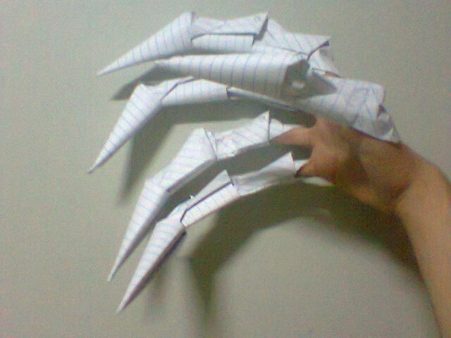
Enter the chaotic mess of scrap handouts cut into paper strips, twisted in every shape and form. I eventually settled on a staggered petal design, vaguely reminiscent of origami claws from my elementary school days.
Step 1: Intro to Lighting Concept


How does the light work? A coin battery is snugly fit on the side of the base, sandwiched in the layers. To turn on the light, you roll it one direction (depends on your design). To turn the light off, you roll the battery back to the original position. Simple, cost-effective, relatively robust.
And how is this done? You have two terminals of an LED, which are soldered to longer pieces of thin wire to lengthen the terminals. One wire wraps around a loop in one layer of the base while the other wire routes down to the layer underneath before wrapping around a loop in that layer below. Then the battery is fit into a pocket in a layer in between those two layers so that one side of the battery is in contact with only one of the terminals. To have the "roll forward for on, roll back for off" functionality, you have different sized loops. One loop is small enough that it'll be in contact with the battery only when you roll the battery forward.
Step 2: Materials
- paper (Plain printer paper will work fine, though I used some spare sketchbook paper since I knew that its porosity makes it glow better)
- glue
- LEDs (simple 1.5-2V ones are fine)
- 3V coin battery (I used a CR2032 because its thickness is roughly 3.2mm, or around 1/8in. The plywood I used was 1/8in thick, which works perfectly with this battery -- you'll see later why the thickness of material matters)
- scrap paper (I encourage you to come up with your own 3D quilling designs. Test out random ideas, from ways to cut your paper strips to ways of twisting them before gluing. Perhaps you'll use scalloped scissors to cut your strips, resulting in an interesting texture -- experiment away!)
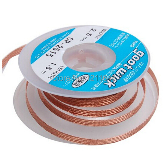
- wire/solder wick (can be anything, from copper strands stripped from scrap electronics to jewelry wire, but it is HIGHLY suggested that you use THIN wire. The thinner it is the better, since it'll need to be sandwiched between layers, but the thinner it is the easier it'll snap so be careful. It's hard to find a compromise between thinness and strength for wire, but I eventually settled with solder wick, which has a strong braid that's also very flexible. Perfect!)
- laser cutter (Full Spectrum hobby 20x12in)
- vector graphics software --- I used Adobe Illustrator (OPTIONAL but for those who want to customize their laser cutting designs)
- soldering iron (OPTIONAL but suggested for robustness)
Step 3: Circuit Design of Laser Cut Layers

I attached the Adobe Illustrator and pdf files (batteryPlatform.ai/.pdf) to this step, but I also included pictures and walkthroughs for how I designed it (next steps) so you can see more clearly how it works.
The base design consists of four main layers:
The first layer just has two holes in the center for the LED terminals to poke through. This is just so the wires start out in the middle for routing later.
The second layer has three holes. The left-most hole close to the bottom edge is for the left terminal to go through and avoid the loop that the right terminal will make. The middle and right-most holes are the holes that the right terminal will go through to make a loop. The LED terminal goes down the middle hole and back up through the right-most hole to make a diagonal which will interface with the top of the battery once it's inserted.
The third layer features a slot on the right side where the battery will slip into for sliding on/off. It also has a hole in the bottom right for the left terminal of the LED to go through to make it to the fourth layer for looping.
The fourth layer has two holes that the LED's left terminal will go through to make a loop that interacts with the bottom face of the battery once it's inserted. The terminal goes down through the hole closer to the bottom edge and back up through the other hole before wrapping around where it went down in order to fully close the loop.


Step 4: Designing for Laser Cutting


You can see the designs on the previous steps, but this step briefly goes over how the shapes are made and positioned. Mostly on this step is showing how third layer's slots are made from splicing together two circles, some lines, and a square. There's also a picture on using lines to outline where your wires will cross so that you can see where to position your circles for the wire to go through.
In any case, see the notes in the pictures above for step-by-step instructions. Quick nutshell: for each layer you are designing, put an slightly transparent/faint copy of the layer above it so you can see how the wires will come down. Draw a line indicating how I want my wire to pass through the layer, and add circles at its endpoints before deleting that line.
BE SURE that your lines indicating wire position make sense; they have to start where they ended on the previous layer (since the wire is one whole strand...
Step 5: Tips on Text


Typography: reliant the art of selecting good fonts. I was taught never to use a default font that anyone recognizes (Arial, Calibri, Cambria, Georgia, etc.) so I went wild with testing different fonts I had that matched the "tone" of my piece. Since this is sort of a product demonstration project for UMakers, I wanted to include some sort of plug/advertisement. For the font, I wanted something slightly professional but not too formal. A bit of a techy touch, so straight lines and fewer curves. I also decided against serifs (except Jura, one of my favorites) in the end since I tend to associate that with business, but UMakers is a fun, hobby makerspace rather than business/marketspace.
Since the real estate I had was less than 2 square inches, I had to use small text to fit in addresses and such. With such small text, I was a bit worried that the raster setting might create scorch marks that would interfere with the text visibility, so I wanted to do a quick vector cut rather than rasterized text (so cut fast in one go at medium power as opposed to cut fast in multiple passes at low power. In this case, you have to select a "single-line font" that doesn't have a stroke, and thus has only a single line through it instead of the standard outline going around each letter for regular fonts. These special single-line fonts are commonly from the Hershey subset of fonts (fonts, not chocolate!) which you can download for free on the internet.
Alternatively, if you're not afraid of rastering, go ahead and do that at a faster-than normal speed to avoid scorching. I actually went with this option in the end since Hershey fonts weren't working well on my computer for some reason.
Step 6: Streamlining the Cutting

You have four squares for each layer, but rather than offsetting them for cutting, you can just overlap them edge to edge (second picture above). The problem is that you now have some lines traced twice: when you have two overlapping edges from putting boxes together, the laser will make two passes on the overlap, scorching your wood even more. To fix this, just be sure to delete the double lines where you connected the boxes. They will appear darker than single lines, though it may be hard to differentiate for those with bad eyesight.
To delete the double lines, you might need to cut your objects. Since these are squares, you definitely need to (Illustrator considers squares to be one object instead of four lines). Use the scissors tool (press "c" since it's a hotkey or click on the scissor icon that's on top of the eraser tool) to cut at the vertices before selecting the specific line to delete.
Step 7: Laser Cutting


Depending on your model, instructions are different so I'll let you handle this. In any case, you should end up with pieces as shown above. Stain the wood as you'd like (I ended up choosing a dark walnut for one variation).
Step 8: Prepping Paper Strips


This wouldn't be a quilling project without paper strips, so grab your paper and scissor.
Begin by folding your paper in half (or at least so that you have 3 inches of overlapping paper). Mark off at every 0.5cm on the bottom edge. Use those marks to cut 0.5cm thick paper strips, folded in half due to that initial fold. For each petal of the final flower, you need five strips, so if you have five petals, then you'll need 5x5 = 25 strips of paper.
Then take a strip, mark off 1" from the folded edge, flip it over, and mark off 1" from the folded edge on that side too. For the next strip, mark off 1.25", 1.5" for the next, 1.75" for the next, 2" for the next: These are the five sizes of paper strips to create each petal of the flower. Make a set of these lengths for each of the petals you want (six petals is pretty much the max, since it's hard to add more petals around in a circle.
Take a marked strip and put a dot of glue on one of your pencil marks. Line up the other pencil mark on top of the glue before pressing down to glue the two sides of the paper strip together. You'll end up with something that looks like a fish. Repeat for all your paper strips, and allow all of them to dry a bit (10 minutes..) before continuing.
Step 9: Forming a Flower


Now that you have your five sizes of petals, begin stacking and glueing them together: take your longest size (2") and dab glue at where the two sides intersect (where the previous dot of glue went). Put the next longest size (1.75") on top of that dot of glue, and repeat until the 1" paper strip. Set this aside to dry for another ~10 minutes as you glue more petals together.
Once all strips are glued and dried, trim off excess edges to a point (see fourth picture above). Cut out two small circles; these will hold your petals together. Apply glue on the trimmed edge of a petal and arrange in on one of your circles so that the point of the petal is at the circle's center (fifth image above). Continue around until all petals are fixed to that circle. Glue the other small circle on top of that to have all petals sandwiched between the two circles that you cut out. Let this dry at least 20 minutes (trust me, longer is better so that you don't have to deal with a flower breaking apart in your hands.. talking from experience) before continuing.
Step 10: Electronics


Poke the two terminals of your LED through the middle of your flower. Bend them 90 degees around 5mm from the flower's base; explained later in the next step. Grab your thin-but-strong wire (again, I used solder wick) and cut out two ~5 inch strands. Twist the ends around the bent corners of the LED terminals and either twist really well to ensure a good connection or solder for safe measures.
If you do choose to solder, make sure you don't leave huge blobs that might interfere with the wires poking through your laser cut holes.
Step 11: Wiring


The wiring is a bit difficult to explain in paragraph form without pictures (pretty simple circuit though, I assure you), so click on the pictures above to see step-by-step instructions in the note boxes. (transcribed below in case that helps too)
Begin by poking the two terminals of the LEDs through the first layer's two holes. Ideally, put the positive terminal through the hole on the right so that you can have the battery inserted positive side up later on.
Put the second layer under the first layer and poke the right terminal through the right most hole.
Poke that right terminal up though the middle hole in the second layer before winding the end around where it went down in the right most hole. This is where your right terminal ends, so trim and glue.
Poke the left terminal of your LED through the left-most hole and through the only hole of the third layer. You can now fully glue the first and second layers together.
When you press the three layers together, you can see the wire of the right terminal sticking out into the coin slot so it'll make contact with the battery top, and the left terminal sticking out to make a loop in the fourth layer.
Put the left terminal through the bottom hole of the fourth layer like so before bringing it up the top hole and again wrapping the end around where it went down the bottom hole to secure the loop.
Clamp all the layers down down and let the glue dry for half an hour or more for good measure.
Step 12: Finished


Enjoy! As always, leave questions or comments below and I'll get to them when I can.

Participated in the
Quilling Contest 2016


