

Introduction: 3D Printed Magnetic Connector! *UPDATED*


****UPDATE****
With kind help of Gravityisweak we 3D printed the early version of my design so be sure to check out his awesome Intructables! He also earn a 3 month Pro membership for helping me. All photos of 3D printed models are made by Gravityisweak.
Be sure to check Q&A in the last step!
Behind every instructable there is a story, and in this instructable you will read the story too. Idea of the connector mentioned in the title of this instructable came to my mind some time ago, but hey, you might think “did you came up with just an idea of a connector?” Well, actually no. The idea came out when I was designing my other project (you can check it out in other instructable soon) I need a connector that can have variable amount of connections. It has to be “quick snap” so the user can quickly connect and disconnect two parts of the product.
Recently I started to study in university, so now I ‘m Industrial Design student so I thought “why not to use the knowledge that I get at the university in my projects?” It’s my second semester at the university, so… Industrial Designers! Bear with me if I make any mistakes in designing this connector. What I want to hear in comments is constructive criticism, suggestions of how we can improve my design because the success of the good designed product lies in teamwork and I love interacting with people here, at Instructables ;)
In this instructable I will cover the following steps of designing. We will:
- decide what we want to create, and set our criteria
- sketch some ideas and decide which one would work best
- figure out our basic dimensions and start modeling the part in 3D CAD software
- check the files so they can be 3d printed
- I will prove that some things can be done at home - we will make copper connectors.
And I will do some rendering work to show you how it would look like.
Step 1: What We Want to Do and How It Should Be Done?


Right.
We know what we want to do. So what now? We have to figure out our criteria.
We are going to make a magnetic connector. We have to decide what our criteria are. Let’s make a list.
We want it to:
-be possibly as small as possible
-connect/disconnect easily by user but it should make also a firm connection
-avoid reverse connection, we don’t want any shorts and burned circuit
-it should be mounted in the casing easily just by gluing it
Now let’s draw our ideas having regard to our criteria.
We will need following tools during the process of designing:
-paper (actually a lot of it if you have a lot of ideas)
-pen and pencil
-3D CAD software (FreeCAD, tinkercad, design Spark, solidworks, Autocad, any will do) in my case it will be solidworks
-to make the connectors you will need 2mm copper wire, nail clippers, soldering iron and some wire.
-Of course 3D printer would be great to print out the files, but you don't have to have one. You will learn some design during this instructable ;)
Let's GO!
Step 2: Drawings and Variations


If you want to design something you have to make drawings. I mean… You don’t have to be good at drawing, I know a lot of people who can’t really draw but they make beautiful 3D models. However, they draw their ideas too. If you feel like designing your type of connector, go and draw a few different ideas of different shapes, if you don’t just take a look at my drawings. They are including some idea, different variations of a final object.
I drew some of the ideas that came in my mind, REMEMBER!
Don't think too much when you draw!
You should draw your ideas one by one! whatever you think might work. It's not about drawing good ideas. You have to draw as many quick drawings as you can so you can have a lot to chose from!
Finished? Great!
Now chose the idea you like the most. You are going to make a 3D model of it. I have chosen the idea marked with number 3.
Step 3: 3D Modeling and Figuring Out the Dimensions.


*EDIT*
I've uploaded ver1.3 of the 3D models. Now there are holes for neodymium magnets with diameter of 6mm. I removed grooves for the wire, because they seem to not print well on FDM printers as reported by Gravityisweak.
Ver. 1.2 is still available to download for the other printers that are capable of printing thin walls.
I like to make some quick technical drawing before modeling something, just to get an idea what dimensions will work, if during modeling something isn’t as good as I thought I just can change it.
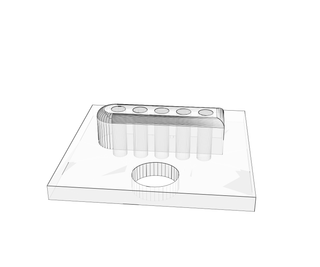
I used Solidworks to do 3D modeling, but I am sure that it can be done using any CAD program like Autodesk 123D, Tinkercad, AutoCAD, Design spark, FreeCAD and probably many others. I made two models – in the “socket” one I changed the dimensions to be 0.25mm bigger than the “plug” one so we can get around 0.5mm overall space to let the plug move a bit. So it’s worth to remember that socket must be a little bigger in order to let the plug to connect.
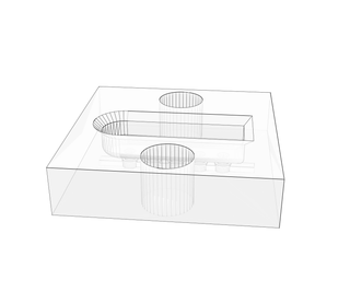
Looking at our criteria there is one thing that we forgot about. We have to make it one way. It means that we can connect the plug only one direction so we can avoid shorts, and inverted polarity that can cause damage our circuit connected to the socket. I achieved that by making one side of the connector rounded. Now we can avoid potential shorting the circuit or reversing the polarity.
My version is meant to be under a casing, so the plate is used to glue the connector to the case. The connector is 5mm long, so if the case shell is 1mm thick i have only 4mm outside the case. The socket is designed to be 4mm deep regarding the case shell thickness. Since this is parametric model, I am able to adopt it to any casing I will be using.
I made a groove at the back of the moving connectors (in the socket one) so we can place there something like rubber or foam to allow connectors move to achieve better contact. I hope that will give them some spring-like action ant they will press against the contact of the plug.
There is place for wires also, after soldered to connectors they can be glued inside the guide holes.
The models have been prepared for 3D printing, they are "watertight" and checked with netfabb software. They should print nice and without problems ;)
If you like my work and want to help me, please visit my pinshape account: HERE
You can buy files there for symbolic 1,30$. It is not lots of money but it can help me in future projects. THANK YOU


Step 4: Making the Copper Connectors !


At first I thought that it will be difficult to make such small connectors that would be suitable for this project, but I came up wit an excellent idea!
As you can see there is need to make 10 copper connectors that are 2mm in diameter and about 2-3mm long. Making the connectors on the plug is easy since they don't move. So i will show how to make moving connectors for the second part of the connector.
You need a nail clippers, and 2mm copper wire. What I do is sand one end of the wire with sandpaper to make it flat, and then I put it into nail clippers like I try to cut it but I rotate the wire until it splits. And there is our connector ;) it just need to be soldered onto wire, but this shouldn't make any problem to you ;)
Step 5: Thats All! (well... Not Really.)
By the word of ending we can consider what project would it be suitable to use it for... Well... I am working on a project that will use this connector. Basically it will connect magnetically two parts of the case, two modules- battery and the main body. Stay tuned to see my next Instructables! It can be used as a charging port for your project, maybe you want a magnetic docking station? Tell me how would you use it in your project! If you use it don't forget to send me a link so I can see it!
If you reading this you probably enjoyed my Instructables or at least it made you interested, so why not spend a while and tell me if you like it in the comments? ;)
Thank you for reading, and being with me for last few years here at Instructables!
Again as I said in intro - leave me a comment! tell me if you like my idea, leave some constructive criticism, and if you made it make sure to post a photo! I love interaction with my audience!
This instructable takes part in a 3D Printing contest, so consider voting on me ;)
See you in another instructable!
You can follow me @KonradSzmit on twitter. I have some projects waiting to be published. There is Bench power supply project, 3D printed ninja shoes (waiting to be modeled and 3D printed ), and ambitious projects that involves 3D printer in making a custom bike ;) So stay tuned for more!
by kondzio29
Step 6: Foam Board Prototype to Prove That It Will Work! *UPDATE*


So, I made a working prototype out of foam board, it was a bit difficult to cut out, but finally it works!
There are only two connectors, because I just wanted to check if it will work as it should, just to prove that this design is working. The Foam board prototype have almost the same dimensions as the 3D printed one. If you want an separate instructable on how to make this type of connector but by hands tell me in the comments!
*EDIT*
With help of Gravityisweak Instructables user my design is finally printed! There is place for improvements, but overall I am happy with first results.
Step 7: Q&A
Okay, so there is Q&A :
Why there is only version that is meant to be mounted in enclosure?
I am still modeling the version that can be mounted on the cable. Stay tuned!
Dude! Did you see apple magsafe? You should try to make it!
Yes. Aaaand no. I will not even try to remake magsafe. Aplle has its own design and I have mine too.
Can I use your connector in my project?
Sure! As long as you give me a credit. Don't forget to tell me about it! I want to see your creations!
Is it final version of the connector?
No. As long I don't have 3D printer I can't prototype new ideas. Yes yes... I know... shapeways, sculpteo and stuff... I have so many Ideas that I cant afford paying for each prototype and paying shipment. It's time consuming to wait for the prints also.
So... You don't have 3D printer?
Nope. Not yet. But I am trying to make thing without it (foamboard version of the connector), however my life would be a little easier if i had one. Thanks to the great community here at Instructables I was able to get my design printed this time.

Participated in the
Explore Science Contest

Participated in the
3D Printing Contest

Participated in the
Pi/e Day Contest


