

Introduction: 3d 4-Dimensional Tesseract Hypercube Model B TJT4/6


If you do not wish to create your own model in 3d-modeling software, you can take the easy way out and just download my model for free at:
http://www.123dapp.com/AssetManager/Publisher?stgAction=getProduct&intProductId=603631
If you wish to 3d-model your own 4d hypercube, I can offer instructions for Rhino. If you want to try some 3d-modeling software for free, either get Rhino's evaluation copy at:
http://www.rhino3d.com/download.htm
...or some excellent, Free 3d-modeling software at:
http://www.123dapp.com/create
Recommended Materials and Processes:
ï· Computer with internet access
ï· 3d modeling software (or download my design for free)
ï· access to 3d printer (I use Shapeways.com)
We experience our lives in 3 dimensions. Einstein showed we live in 3 spatial dimensions with a 4th dimension of time. This is the spacetime continuum. The 4th dimension upon which this instructable instructs is the spatial 4th dimension.
Dana Carvey as "the Church Lady" used to ask something like, "isn't that spatial?" Indeed it is.
Were we stick figures living out our lives, strolling around on a sheet-of-paper Universe, it would be maddeningly confusing for someone to elucidate the "3rd dimension" to us when our entire culture has been defined by "up" & "down", "left" & "right".
Nonetheless, we can do it. Should we wish to transcend the limitations of these measly 3 dimensions we must consider that which we have not previously experienced, back on the sheet-of-paper Universe.
Step 1: More Description of the 4th Dimension


This step of the instructable is included in an attempt to make basic 4-dimensional geometry clear. If you already understand 4d or don't wish to read it right now, skip to the next step.
0 – A point is a hypercube of dimension zero.
1 – If one moves this point one unit length, it will sweep out a line segment, which is a unit hypercube of dimension one.
2 – If one moves this line segment its length in a perpendicular direction from itself; it sweeps out a 2-dimensional square.
3 – If one moves the square one unit length in the direction perpendicular to the plane it lies on, it will generate a 3-dimensional cube.
4 – If one moves the cube one unit length into the fourth dimension, it generates a 4-dimensional unit hypercube (a unit tesseract).
Step 2: Make a Box


This tutorial instructs how to build a 4d hypercube model in Rhinoceros 3d software, then you're in the right place.
1. Open Rhinoceros 4.0
2. On the bottom navigation bar click Snap so the model creation coordinates will snap to the grid. (Figure 1)
3. On the bottom navigation bar click Ortho so the model creation coordinates will be symmetrical. (Figure 1)
4. Click Box tool on the left navigation bar to create a rectilinear solid. (Figure 2)
5. Click on three corners of box. (Figure 3)
Step 3: Boolean Subtraction


6. Right Click on Zoom Extents to zoom into model in each quadrant. (Figure 4)
7. Click on three corners of second box. (Figure 5)
8. Click on second box to select it. Then click on Move tool. (Figure 6)
9. Click on grid, then click second time one unit down to Move box. (Figure 7)
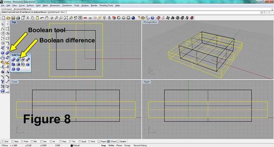
10. Right Click on Boolean tool. Left Click on Boolean Difference. (Figure 8)
Step 4: Copy and Paste


11. Left Click on smaller box, then Right Click. (Figure 9)
12. Left Click on Zoom Dynamic, then Right Click. Move cursor over Lower Left Quadrant. Hold down left mouse button and drag down to zoom out. (Figure 10)
13. Select object by Left Clicking on it. Select Copy Tool. (Figure 11)
14. Click in then on the upper part of the Lower Left Quadrant. Click a second time in the lower part of the quadrant. (Figure 12)
15. Click three corners of another box. (Figure 13)
Step 5: Copy Some More


16. Select Copy Tool. Click to make 3 copies of box in other 3 corners. Add a fourth copy to the side. (Figure 14)
17. Hold the Shift key, then select each of the 6 objects composing the now-created cube.
18. Select Edit > Group > Group.
19. Select Copy Tool. Copy entire cube group. (Figure 15)
20. Use Move tool to move cube group to right in Upper Left Quadrant. (Figure 16)
21. Select extra box. Then Edit > Layers > Change Object Layer. Select the Red layer. Click OK. (Figure 16)
Step 6: Add Diagonal Boxes


22. On the bottom navigation bar click Snap and Ortho to turn them off.
23. Select, then use Move tool to move the tall, skinny box in Lower Right Quadrant. Move the box so that its top left corner is in the top left corner of the cube group. (Figure 17)
24. Select, then use Move tool to move the tall, skinny box in Lower Left Quadrant. Move the box so that its top left corner is in the top left corner of the cube group. (Figure 17)
25. Select, then use Rotate tool to rotate the tall, skinny box in Lower Left Quadrant. Left Click on the top left corner of the tall, skinny box. Rotate the tall, skinny box so that its bottom end intersects the top left corner of the lower right cube group. Repeat this action in the Lower Right Quadrant. (Figure 18)
26. Right Click on Zoom Extents to zoom into model in each quadrant. In Lower Right Quadrant, Copy the skinny box to each of the other three corners. (Figure 19)
27. In the Lower Left Quadrant, hold the Shift key, then click one of the lower, rotated skinny boxes to select a second object. (Figure 20) Click Ortho to turn it on. Click Copy, then copy these two boxes from the left to the right corners. (Figure 21)
Step 7: Finish & Save


28. Double-Click the word Perspective to maximize the Upper Right Quadrant perspective window. Hold down the right button to rotate the objects to this approximate angle. Double-Click the word Perspective again. (Figures 22 & 23)
29. Select Copy, then copy the now-selected box in the Lower Left Quadrant to the right side of the model. (Figure 24)
30. Double-Click the word Perspective to maximize the Upper Right Quadrant perspective window. In the Upper Right Quadrant perspective window. Hold down the right button to rotate the objects to this approximate angle. Select box shown. Double-Click the word Perspective again. (Figure 25)
31. Select Copy, then copy the now-selected box in the Lower Left Quadrant to the right side of the model. (Figure 26)
32. Hold the Control key then click the A button to Select All. Then Edit > Layers > Change Object Layer. Select the Red layer. Click OK. Right Click on the Shade tool to shade all viewports. (Figure 27)
33. Double-Click the word Perspective to maximize the Upper Right Quadrant perspective window. Hold down the right button to rotate the objects to check and examine the final product. (Figure 28)
34. Double-Click the word Perspective again. File > Save As > Save as type .STL > Save
Step 8: Print It UP!


35. Upload to www.shapeways.com for 3d printing in material of choice.
Some of the available materials include nylon, alumide, stainless steel, gold-plated stainless steel, bronze-infused stainless steel, sterling silver, ceramic, ABS plastic, ceramic, gypsum composite, and so on.
I ordered mine in Shapeways' "White, Strong & Flexible". It is inexpensive. It is strong and flexible. Here's the description:
http://www.shapeways.com/materials/white_strong_flexible

Participated in the
Make It Real Challenge


