

Introduction: 3d Print Your Own Rover


Over the summer I found a fun thing for my kids to get involved with which involved coding and robots as well as giving them the chance to own the materials they had learnt to use. They had a great time, building codable devices for games and light displays as well as rover type robots consisting of a printed plastic motor mount some tongue depressors and a lot of elastic bands to hold the crumble control board, the batteries etc. at the end they got to keep the electronics, wheels and the motor mount.
when we got home I decided to design and print a set of parts that would form the body of a more substantial rover for them to play and code with. This instructable covers the requirements and steps used to build the two required sets.


It also holds the stl files with will enable you to recreate your own rovers. if you like this guide then please consider voting in the competions entered into.
Thanks for reading.
Step 1: The Motors


The first thing to consider was the motors - the original mount was sufficient to hold them but not very much else as mentioned to build a bot with it needed effectivley sealing wax and stringto hold it together. so the first task was to take measurements from it and recreate it in sketchup.
At first i was going to use the full version installed on my computer, however Trimble the new owners of the application had included details of their new FREE online version so i thought to give it a try and have found it to be an excelent tool. Its called my sketchup - if you want to try it just enter this into google it will take your straight there.
Step 2: My Sketchup


To get to the my sketchup site use the following link
https://www.sketchup.com/products/my-sketchup
The app works almost exactly like the full program and you can have a play straight away, but to save any of your work you will need to log in which you can do using your google account.
My design was initially made of four components
- Motor mount (Based on the double motor clip by Mike Cargill, UK STEM)
- Crumble board mount
- Battery mount
- Marble Wheel (from Thingiverse - https://www.thingiverse.com/thing:609498 )
Motor Mount
Once I had taken the measurements from the original mount and created the sketchup file - I set about improving it, this included
- Adding larger holes on the rear surface - these would later be used to anchor the crumble board mount
- Adding more holes to allow wires to pass from the motors to the board as well as for other wires, such as sensor or sparkle connections.
- Adding a board on the front of the module - this is for attaching sensors and at the end of this instructable the distance sensor is attached to it, but others could be used.

Crumble board mount
The next board for design was the Crumble mount this was easy in sketchup - you simply start by grouping the previous unit so that anything else added does not attach to the next one. The you are free to use that unit as the starting point - working this way ensures that the finished model fits together as intended. the design features for this part are
- On the front end a raised bead - this works with the cylinders a little further back to clip the crumble mount onto the motor mount - the notch in this bead also helps locate the board correctly and keeps the whole rover straight.
- A support wall mid way on the mount - this has a large hole in the middle to allow for wires to pass through.
- The wall has concave sides, which was a later addition as I found that the initial attempt was fouled by the motors when connected to the motor mount. - It also has a tenon which is used to attach to the battery mount.
- At the rear is the actual board mount - this originally just supported the board and held it in place via the printed clips at each end. This support also had a channel running its length - again a way of passing and hiding wires. I later added a cut out section mid way to allow for wires to come out of the side underneath the board.
- The mount also has a rounded rear section as a nice place to attach the marble wheel under it.

Battery mount
Like the parts before the battery mount went through a series of growth spurts. The initial design was a simple tray open at one end into which the battery tray would sit. It had a slot mid way to sit on the tenon of the crumble board support wall and two small rails on the underside to hook onto the motor mount. However when printed the support on the under side was limited resulting in a poor print finish, so a redesign was required. I also noted that the battery box did not sit level in the tray. The redesigned unit has raised section to support the battery box more and is attached to the rover via an additional slot - and tenon arrangement to hold it to the motor mount -(this required a redesign of the motor mount as well - see image below)
Initial Battery mount:

New Battery mount:

New Motor mount:

Rear Wheel
For the rear wheel - I cheated and used the instructables site see the link above - this works on the principle that you should not have to reinvent the WHEEL - pardon the pun

Late additions
With the main part of the rover complete - I decided to make an addition - the crumble board can connect the led lighting units called sparkles and sparkle batons as well as to other forms of sensor - for example an LDR board, so I designed a support frame to fit on top of the battery mount along with a couple of clips that fit into the support and are able to rotate to facilitate the attaching of the various cables needed to make them work.

The completed Sketchup file is attached at the end of this guide as well as being available on the 3D warehouse see the link below to 3d warehouse
Step 3: Printing the Parts


I printed the parts on a Vector 3 3D printer which I built from the 3D Create and Print magazine. For mor information on this printer I have included a link to the magazines web pages http://3dprinter-collection.com/
Be patient 3D printing is not a fast process,however the results can be really impressive, the whole kit of parts took approximately 2 days to print (not including nights - I don't like leaving hot equipment on while I'm asleep)
Step 4: Finished Parts


This section just shows off the finished parts once I had removed the rough bits left from the print process. There is also a picture of the two types of battery mount which clearly shows the support structure I included to level out the battery box in the mount.
Step 5: Putting It Together


Marble Wheel
Attaching the Marble wheel to the Crumble Board mount was simple - it is designed to either fasten using the screws or you could do as I did use superglue. I chose this method as it was quick, simple and I do not intend to separate the two parts.
Motors
These simply snap into the slots as shown in the images - take care to get them the correct way around and remember when wiring up and programming that one is the mirror image of the other and so you can either swap the red and black wires over or ensure that one motor is programmed to go forward while the other in reverse, and vice versa depending on which way you want the rover to go. (NOTE its easier to swap the cables over - that way you do it once and can forget about it when programming)
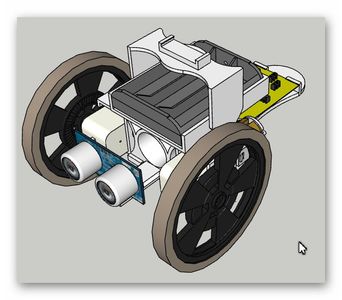
This as hard as it gets - the rest of the parts simply snap together and the wheels push onto the motors.
Job done for construction
Step 6: Wiring and Programming


The software to program the crumble board is freely available from the Redfern electronics at the following link
https://redfernelectronics.co.uk/crumble/
The distance sensor is wired to the crumble as per the flowing diagram taken from the Redfern web site.

The battery pack attaches to the board as expected plus to plus and minus to minus with the two motors attaching at the lower part of the board where it says motor 1 and 2, remember to swap the connections for one of the motors.
Programming
As with a lot of programming applications the crumble app is a drag and drop system. The user drags the various blocks onto the screen and builds the program up prior to uploading it to the rover via a USB cable
The following is the program used to allow the rover to mover around the room sensing obstacles and avoiding any located.


The next thing to try will be to get the Sparkles working to give the rover multi colored lighting.
We've had great fun with the project and both my kids enjoy playing with the sets I have printed for them
Thanks for reading - The files for download are on the next section.
If you enjoyed it please consider voting for this in the competitions
Step 7: Down Load Files
Attachments


Participated in the
Automation Contest 2017

Participated in the
Plastics Contest

Participated in the
Make It Move Contest 2017


