

Introduction: 4 DOF Mechanical Arm Robot Controlled by Arduino


Recently I bought this set at aliexpress, but I could not find an instruction, which fits for this model. So I end up in build it almost twice and do a lot of experiments to find out the right servo mounting angles.
A reasonable documentation is here but I missed a lot of details and some arms are mounted at the wrong side, so do not rely too much on this.
After I wrote this instructable, I found the real onehere. The only difference is, they mounted the back arm of the right forearm on the other side of the rack and therefore need a spacer at the upper joint.
Another Instruction can be found here.
So here Is the quick instruction for this model :-) but with improved software.
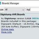
The software to control the Robot Arm manually or by IR remote is available at GitHub and included in the ServoEasing Arduino library as the RobotArmControl example.
Step 1: The Base

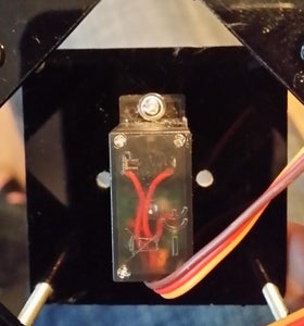

The servo angle for this picture is almost 90 degree and take care to build the plate in the right orientation, it is not symmetric!
if you tighten the screws too much, the extra mounting plate can break. In this case you can drill two 1.5 mm holes at the short sides of the servo opening for the screws delivered with the sero for this purpose. If you do not own such a tiny drill, you can use a hot needle to create the holes.
Step 2: The Arm

Best assemble this part next!
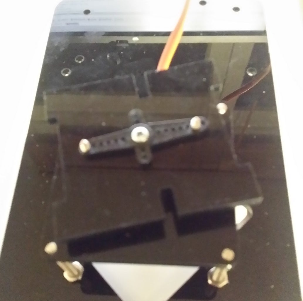
Step 3: Horizontal and Lift Servos
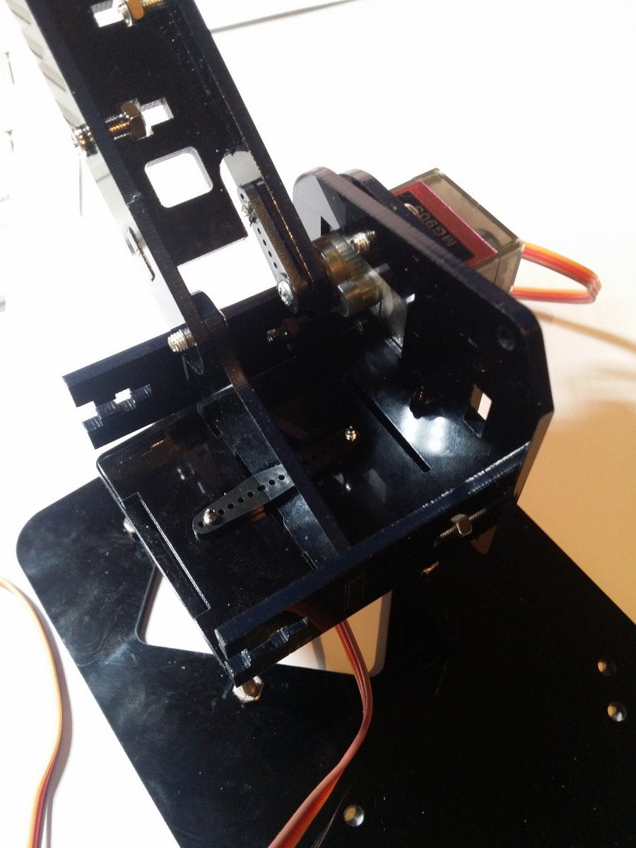


The angle for the right (horizontal) servo is 60 degree for the arm pointing upwards or 180 degree at the most forward position possible.
The angle for the left (lift) servo is 0 degree for the attached arm being vertical. But since you can mount the horn only at 18 degree steps, it ends up for me to have 15 degree at the vertical position.
Step 4: The Arm

No spacer needed here.
Step 5: The Claw
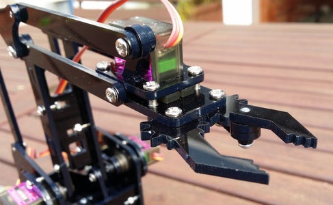


I set the servo angle so that the claw is open at 0 degree and close at 65 degree.
One spacer is needed for the left arm mounting and two are needed for the claw mechanic.
This are the only spacers needed for the whole Robot Arm.
Step 6: The Arduino

The software is available at GitHub and included in the ServoEasing Arduino library as the RobotArmControl example. It can also be useful to help setting the servos to the right position for assembly, using the Arduino Serial Monitor. And be careful, the auto move function will start in 30 seconds if there is no action at the potentiometers after reset :-).
The software supports also IR control of the arm.
Step 7: Inverted Kinematic
The auto move and test move use inverted kinematic for the movements. The effect is best observable at slow speeds.

Participated in the
Arduino Contest 2019


