

Introduction: 4x4x4 LED Cube (Arduino Uno)

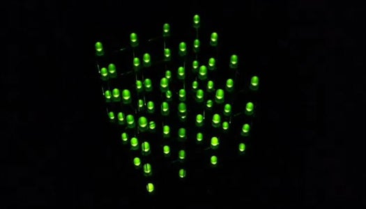


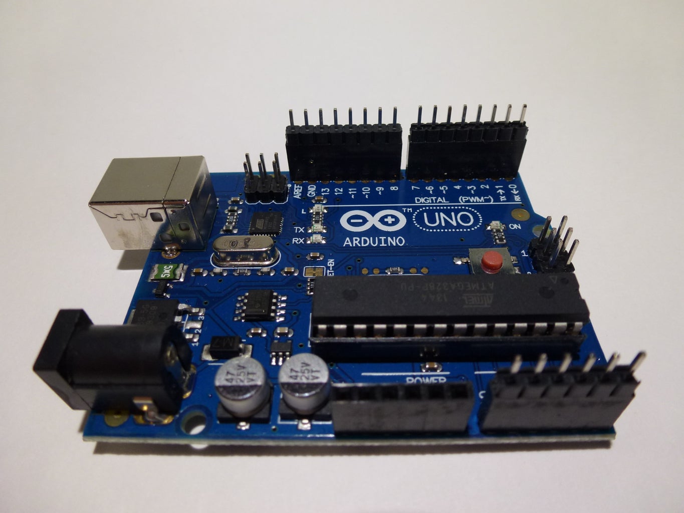
In this tutorial I'll show you how to make a 4x4x4 LED cube for around $15.00. The cube has 64 green LEDs which make up it's 4 layers(positives) and 16 columns(negatives). These are all wired to a Arduino Uno. An Arduino is a single-board microcontroller, intended to make the application of interactive objects or environments more accessible. The hardware consists of an open-source hardware board designed around an 8-bit Atmel AVR microcontroller, or a 32-bit Atmel ARM. I programed code(sketches) for the Arduino Uno to controll the individual LEDs to display patterns for this captivating desktop light show.
Watch The Video:
-----------------------------------------------------------------------------------------------------
Besides the fun of making and posting this instructable, this project is an entry for the Tech, Teach It, and Epilog Challenge VI Contests. I would really appreciate your vote!
Please click on the orange vote ribbon in the upper right-hand corner of this
page if you enjoy this Instructable.
-----------------------------------------------------------------------------------------------------
Step 1: What You Will Need:

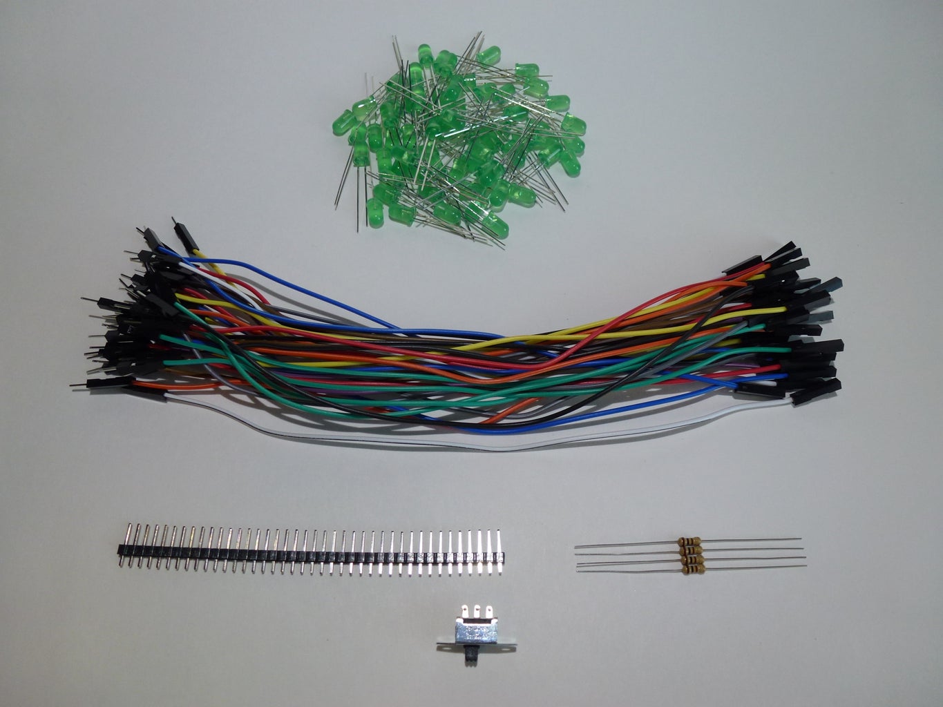

Parts/ Materials:
- 64 Diffused LEDs $2.00
- 4 100 OHM Resistors $1.00
- Pin Header $0.50
- Slide Switch $1.00
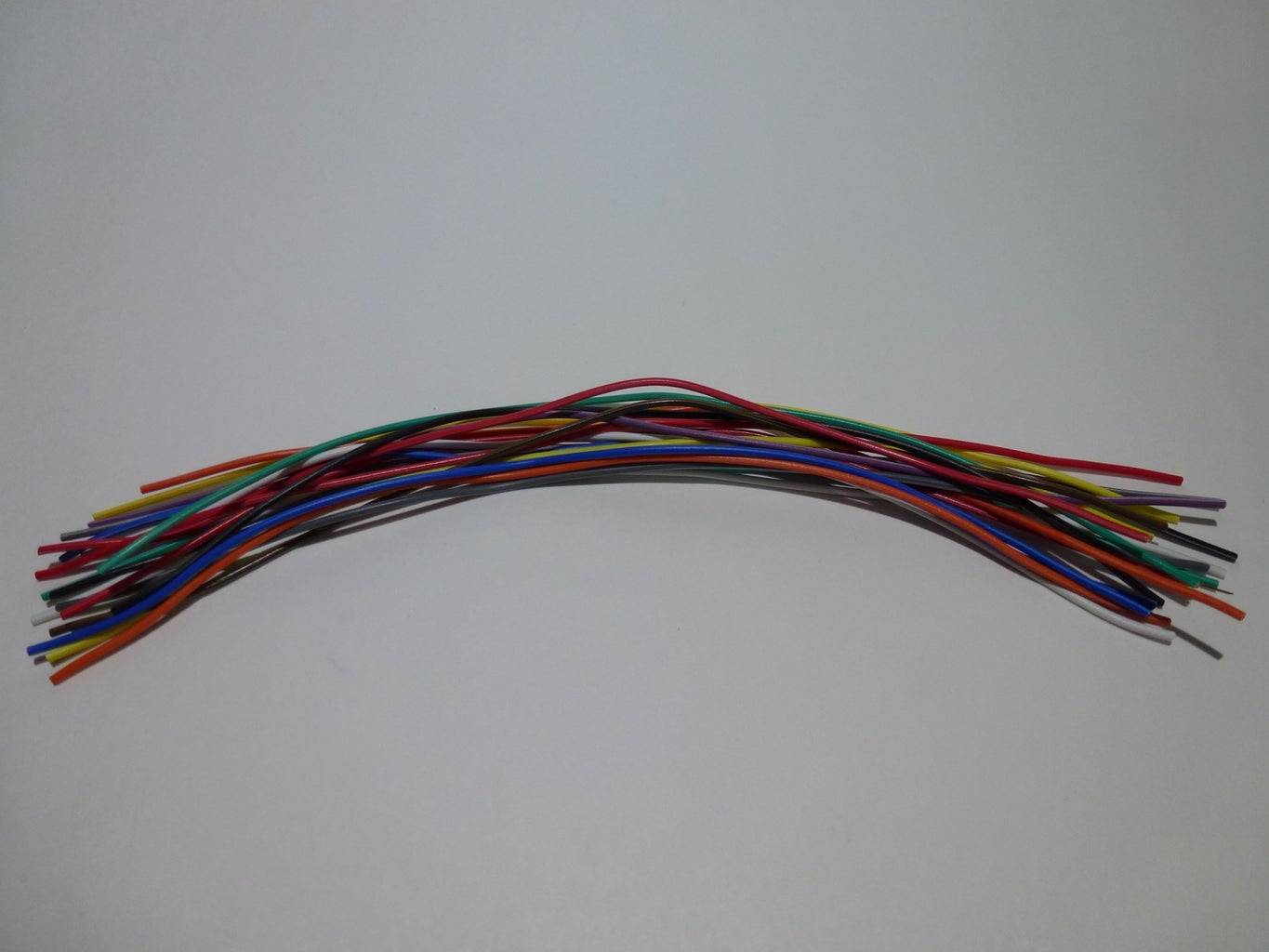
- Wire $0.75
- Craft Wire $0.25
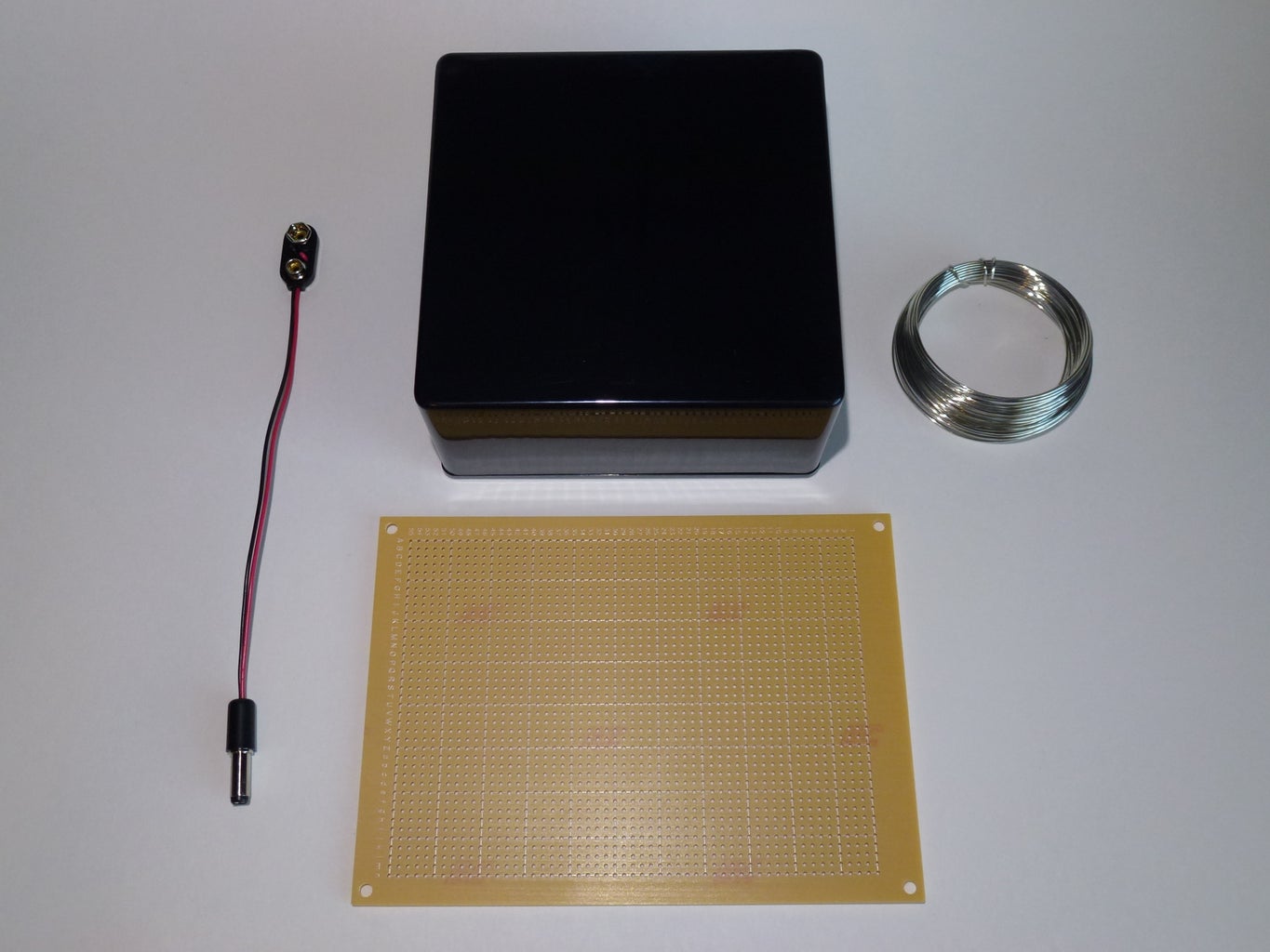
- Perf Board $2.00
- Project Box $6.00
- 9V Power Supply $1.00
Total Cost: $14.50
Tools/ Adhesives:
- Arduino Uno
- Drill
- 1/16" Drill Bit
- 5/16" Drill Bit
- Knife
- Straight Edge
- Needle Nose Pliers
- Soldering Iron
- Solder
- Hot Glue Gun
Step 2: Making the LED Jig


First, Start by printing out my 4x4x4 LED Cube Template and paste it to a cardboard box.Make sure that the printing settings are set to actual size and landscape orientation. Next, punch out all 16 LED holes(grey dashed circles) using a pencil. Insert a LED into the individual holes to test the fit.
Attachments

Step 3: Making the LED Cube


Take the 64 LEDs and test them to ensure that they all work using a button cell battery. This may sound tedious but in the end this will safe-guard your your project! Next, insert 16 LEDs into the holes and bend the leads to the direction of the arrows using needle nose pliers. The red arrows represent the positives(anodes) likewise the blue arrows represent the negatives(cathodes). Solder all of the positive leads together and trim off the access of the leads. Now, you might have noticed that there are two gaps in the layer of the positive leads. This can be solved by straightening a length of craft wire by pulling both ends of the wire with pliers and trimming two 1" sections that are then soldered in place. After the hole positive layer is soldered together, flip the box over and start pushing the tips of the LEDs out of the holes in the jig. Make sure to do this evenly to avoid bending or damaging the layers structure. Now your first LED layer is finished! Follow this step three more times to end up with four layers. Next, take the four LED layers and solder the negative leads together by stacking the individual layers on the top of each other. Start by soldering the leads in the center, then work out to the leads on the edge. The 4x4x4 LED cube is starting to take shape! Straghten another length of craft wire and cut and bend four sections that will later connect the four layers to the perf board. Finally, solder them in place.
Step 4: Installing the LED Cube


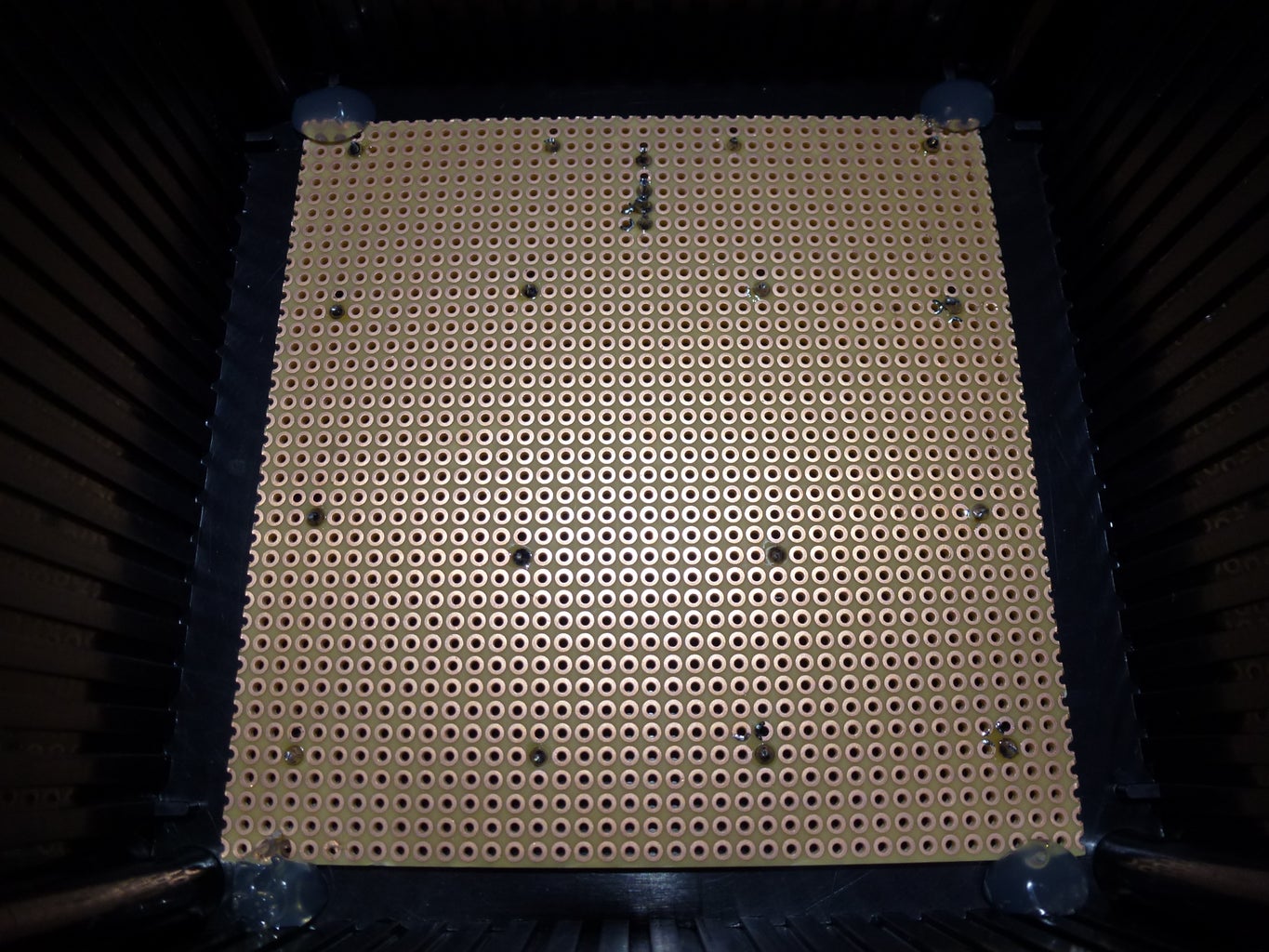
Start by marking an outline of a square with a Sharpie that is slightly smaller than the interior sides of project box on the perf board. Use a straight edge and a knife to score the outline along the lines, then break off the access material by placing the perf board in a vise or on the edge of a table, then apply pressure till the scored sides snap off. Next, drill 20 holes with a 1/16" drill bit for the leads on the top of the project box. An easy way of doing this is by marking the holes where the leads poke out of the perf board and then taping the board to the top of the project box. Next mark the 20 holes on the top of the box through the board with a sharpened pencil. Take the perf board off and drill where the markings are on the project box. Then glue the perf board inside of the box with some hot glue. Make sure that all 20 holes line up with the holes on the perf board. Next install the LED cube by carefully inserting each lead through the holes on the project box. Finally, solder the leads in place, then trim off the access wire.
Step 5: Wiring the Circuit

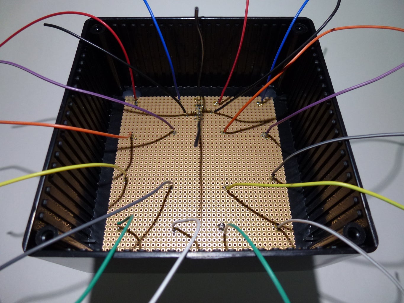
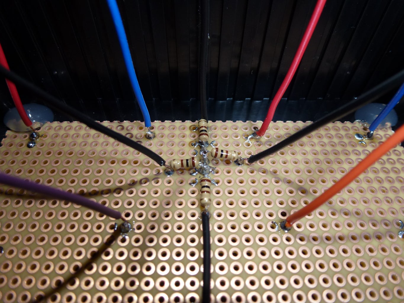

First, snap the pin header in to 3 pieces that fit the Arduino Unos digital and analog plug-ins. Strip and start soldering wires to the 16 digital leads(columns) on the perf board. For the 4 analog leads(layers), solder 100 OHM resisters to the leads then solder wires to each resisters lead. Next strip and solder the opposite ends of the wires to the 3 pin headers. The wiring is setup to resemble a graph with a 3rd dimension. For the columns, there are two axes X and Y. In addition, the layers serve as the Z axis. If you look straight down from the top of the LED cube it looks like the 1st quadrant on a graph except that the origin is (1,1) on the cube. Likewise each LED can be named using the fundamental graphing technique. Lets try an example; look at the demonstrational picture and find A(1,4). "A" means that it is on the first layer and "(1,4)" is X=1,Y=4 on the graph.
Connection Setup:
Columns
[(x,y)-Pin]
- (1,1)-13
- (1,2)-12
- (1,3)-11
- (1,4)-10
- (2,1)-9
- (2,2)-8
- (2,3)-7
- (2,4)-6
- (3,1)-5
- (3-2)-4
- (3-3)-3
- (3,4)-2
- (4,1)-1
- (4,2)-0
- (4,3)-A5
- (4,4)-A4
Layers
[Layer-Pin]
- a-A0
- b-A1
- c-A2
- d-A3
Step 6: Installing the Arduino/ Power Supply
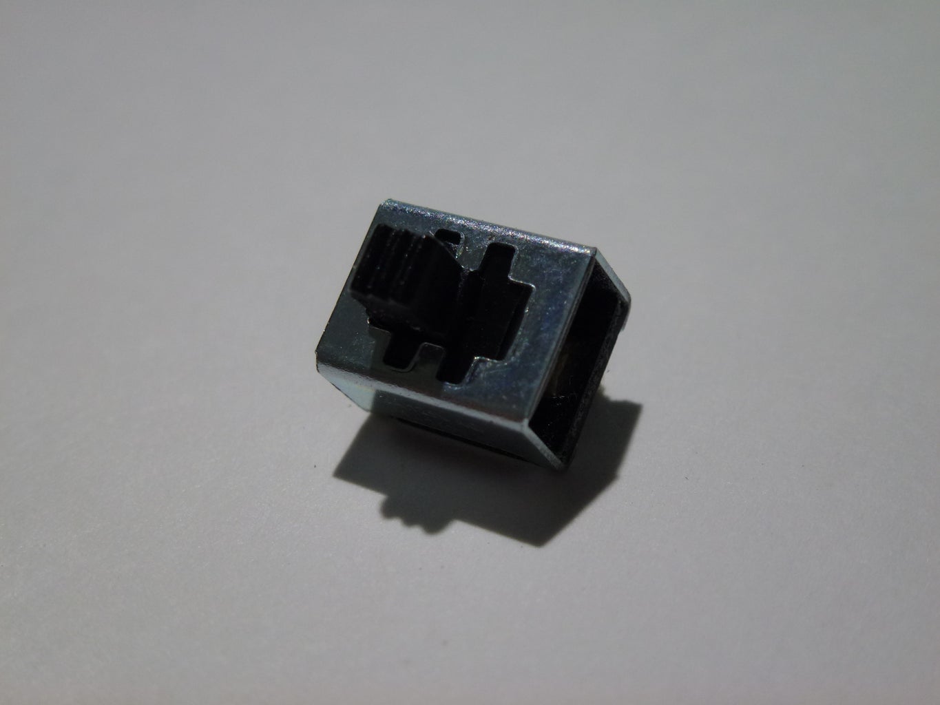


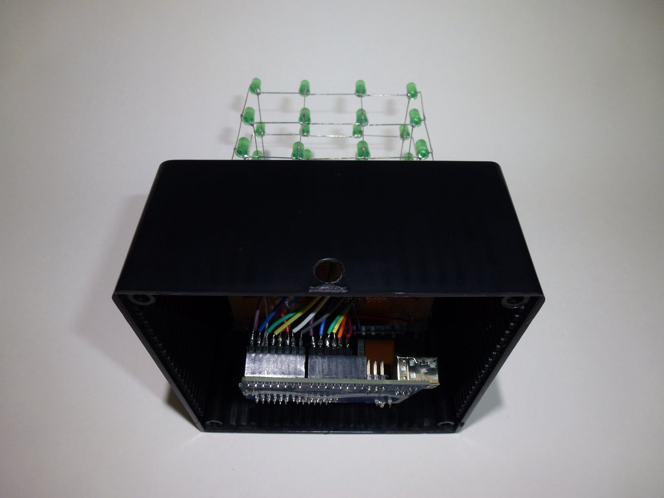

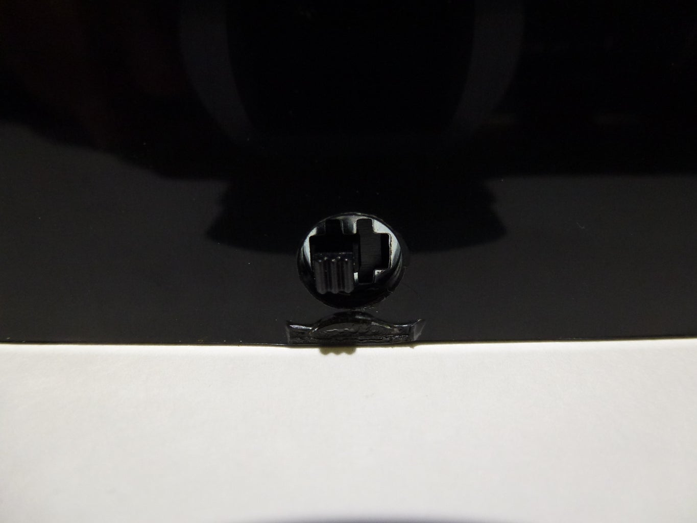

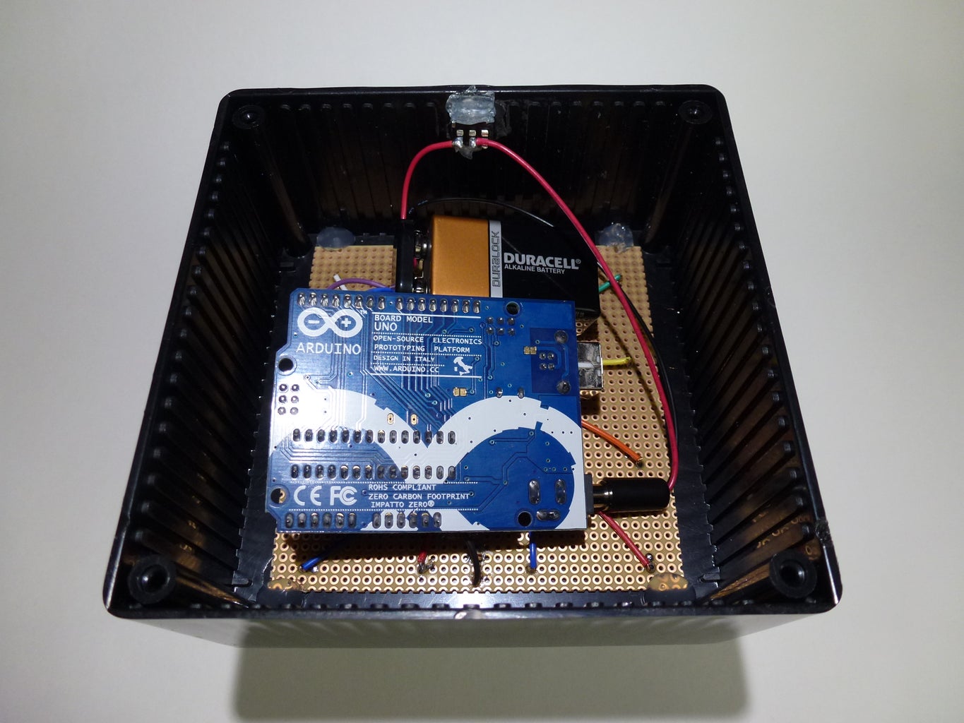

Take the sliding switch and cut the mounting tabs off with the wire snips on the needle nose pliers. Next, cut and strip the positive wires of the power supply and solder the switch to the positive leads. Drill a hole on the side of the project box with a 5/16" drill bit. Make sure to work up to the 5/16" hole in increments of bit sizes. Carve away the plastic ribs in the interior of the box near the hole with a knife, then hot glue the switch in place. Next, plug the pin headers and the 9v power supply into the Arduino Uno. Lastly, upload the code(sketch) to the Arduino then tighten the bottom lid on to project box. Now the 4x4x4 LED cube is finally finished!
Enjoy!
Want more instructables?Please favorite, follow, and comment for more creative builds, hacks, and more.
Thanks, KyleTheCreator
The Code!
I found this sketch online, then I edited it to work for my LED cube. Soon, I'll have my own sketch that will be posted right here, on this i'ble. But for now, if you have any improvements or add-ons to this current sketch, let me know so I can keep it updated:)
Attachments

Step 7: I Made It! Gallery


This is a gallery of the 4x4x4 LED cubes that members of the community have made by following this instructable. If you would like to have your LED cube featured, click the "I Made It!" button to post it in the comments and I will add it right here, in the "I Made It!" gallery.

Participated in the
Epilog Challenge VI

Participated in the
Tech Contest

Participated in the
Teach It! Contest Sponsored by Dremel


