

Introduction: 555 Timer With a Decade Counter and LEDS and Piezo Buzzer;basic Description of Circuit


This circuit consists of three parts .They are a piezo buzzer which produces sound . A Code (program) will play "Happy Birthday " by Arduino through the piezo .The next step is a 555 timer which will produce pulses which acts as a clock. These clock pulses which will go to the Decade counter . The Decade counter will count to 1 to 10 .This will be visible by LEDS blinking in a sequence
Step 1: 555 Timer
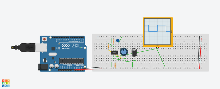

The first part is a 555 timer. The actual 555 timer is the first image . The 555 timer is used electronics.It can used as as a timer and can deliver pulses .
.It is used in alarm circuits and in digital circuits as a clocks .It has many other uses.
The parts are ;
555 timer
1k resistor(brown,black,red)
10 k resistor (brown ,black,orange)
4.7 k resistor( yellow ,purple red)
100k potentiometer
10 uf capacitor;;the large one
0.01 uf capacitor the small one
The 555 timer will have an output of rectangular pulses at pin 3.(see first image)
Look at image to connect the circuit .
The output of the 555 timer is is pin 3. This will go to the pin 14 of the 74HC 4017 . It will act as a clock for the Decade counter .
Step 2: The Decade Counter


The decade counter is the long chip named 74HC4017 It is in the first image .The IC outputs are in the second image .
A Decade counters are an unique counter .Most digital counters are binary .They count in a base 2 system of 0 or 1 .
The Decade counter does too, but count up to 10 in a sequence . The outputs are Q 0-Q9. These outputs will be connected to resistors (1k) and LEDS ,The LEDS will register the outputs and light up(LEDS) in a sequence from left to right . You can count form 1 to 10 by looking at the LEDS light up in a sequence .
The parts for this part of the circuit are ;
74HC 4017 chip
10 1 k resistors
10 LEDS
Step 3: Connecting the Outputs of the 74HC 4017


How to wire up the 74HC4017
Q0 is pin 3 goes to the 1st resistor
Q1 is pin 2 goes to the 2 nd resistor
Q2 is pin 4 goes to the 3 rd resisitor
Q3 is pin 7 goes to the 4 th resistor
Q4 is pin 10 goes to the 5 th resisitor
Q5 is pin 1 goes to the 6 th resistor
Q 6 is pin 5 goes ot the 7 th resistor
Q7 is pin 6 goes to the 8 th resistor
Q 8 is pin 9 goes to the 9 th resisitor
Q 9 is pin 11 goes to the 10 th resistor .
Step 4: LEDS

The next step is to add the LEDS to the resistors .
Connect the positive lead of the LED (the long leg) to the resistor .
The negative leg of the LED goes to ground which is the black leads .
Step 5: Piezo
The parts needed in this part are ;piezo speaker and Arduino and Code for the Happy birthday " song.
The piezo buzzer consists of a piezo crystal between 2 crystals .When voltage is applied across the crystals they push one conductor and pull on the other .This action of pushing and pulling conductors produces sound .
The Code(second Image) is read by Arduino and produces the notes for the song "Happy Birthday ' It is heard from the piezo buzzer
The positive side of the piezo is connected to digital pin 9 .
The ground is connected to ground (see Image)
Attachments

Step 6: Arduino
The next step is easy .
The part needed is Arduino
Connect the 5 volts pin from Arduino to the breadboard .(red lead)
Connect the ground form the Arduino to the ground of the breadboard(black lead)
The video shows the circuit with LEDS blinking and sound(listen carefully )
This circuit was made on Tinkercad .It works .It was a fun project to do .Hope it helps you understand 555 timers and Decade counters and how you can utilize them to make a circuit .Thank you


