

Introduction: 5x4 LED Display Matrix Using a Basic Stamp 2 (bs2) and Charlieplexing


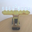

Have a Basic Stamp 2 and some extra LEDs sitting around? Why not play around with the concept of charlieplexing and create an output using just 5 pins.
For this instructable I will be using the BS2e but any member of the BS2 family should work.
Step 1: Charlieplexing: What, Why, and How
Let's get the why out of the way first.
Why use charlieplexing with a Basic Stamp 2?
---Proof of concept: Learn how charlieplexing works and learn something about the BS2. This may be useful to me later using faster 8-pin chips (only 5 of them will be i/o).
---Useful reason: Basically there is none. The BS2 is far too slow to display without noticeable flickering.
What is charlieplexing?
---Charlieplexing is a method of driving a large number of LEDs with a small number of microprocessor i/o pins. I learned about charlieplexing from www.instructables.com and you can too:
Charlieplexing LEDs- The theory
How to drive a lot of LEDs from a few microcontroller pins.
Also at wikipedia: Charlieplexing
How can I drive 20 leds with 5 i/o pins?
---Please read through the three links under "What is charlieplexing?". That explains it better than I ever could. Charlieplexing is different from traditional multiplexing which needs one i/o pin for each row and each column (that would be a total of 9 i/o pins for a 5/4 display).
Step 2: Hardware and Schematic

Materials list:
1x - Basic Stamp 2
20x - light emitting diodes (LEDs) of the same type (color and voltage drop)
5x - resistors (see below regarding resistor value)
Auxiliary/Optional:
Method of programming your BS2
Momentary push button as a reset switch
6v-9vPower supply depending on your version of the BS2 (read your manual)
The Schematic:
This schematic is put together with the mechanical layout in mind. You will see the grid of LEDs set up on the left, this is the orientation for which the BS2 code has been written. Notice that each pair of LEDs have the anode connected to the cathode of the other. They are then connected to one of the five i/o pins.
Resistor Values:
You should calculate your own resistor values. Check the datasheet for your LEDs or use the LED setting on your digital multimeter to find the voltage drop of your LEDs.
Let's do some calculations:
Supply Voltage - Voltage Drop / Desired Current = Resistor Value
The BS2 supplies 5v regulated power, and can source 20ma of current. My LEDs have a 1.6v drop and operate at 20ma.
5v - 1.6v / .02amps = 155ohms
To protect your BS2 you should use the next higher resistor value from what you get with the calculation, in this case I believe it would be 180ohms. I used 220ohms because my development board has that value of resistor built into it for each i/o pin.
NOTE: I believe that since there is a resistor on each pin this effectively doubles the resistance on each led since one pin is V+ and the other is Gnd. If this is the case you should reduce the resistor values by half. The adverse effect of too high a resistor value is a dimmer LED. Can someone verify this and leave me a PM or comment so I can update this information?
Programming:
I have been using a development board that has a DB9 connector to program the chip right on the board. I do also use this chip on my solder-less breadboard and have included an In Circuit Serial Programming (ICSP) header. The header is 5 pins, pins 2 through 5 connect to pins 2-5 on a DB9 serial cable (Pin 1 is unused). Please note that to use this ICSP header pins 6 and 7 on the DB9 cable must be connected to each other.
Reset:
A momentary push reset button is optional. This just pulls pin 22 to ground when pushed.
Step 3: Breadboarding

Now it is time to build the matrix on a breadboard.
I used a terminal strip to connect one leg from each led pair together and a small jumper wire to connect the other legs. This is detailed in the closeup photo and is explained in depth here:
1. Orient your breadboard to match the larger picture
2. Place LED 1 with the Anode (+) toward you and the Cathode (-) away from you.
3. Place LED 2 in the same orientation with the Anode (+) in the connecting terminal strip of the LED 1 cathode.
4. Use a small jumper wire to connect the Anode of LED 1 with the Cathode of LED 2.
5. Repeat until each pair of LED's has been added to the board.
I use what would normally be the power bus strips of the bread board as bus strips for the BS2 I/O pins. Because there are only 4 bus strips I use a terminal strip for P4 (the fifth I/O connection). This can be seen on the larger picture below.
6. Connect the terminal strip for the LED 1 cathode to the P0 bus strip. Repeat for each odd numbered LED substituting the proper P* for each pair (see the schematic).
7. Connect the terminal strip for the LED 2 cathode to the P1 bus strip. Repeat for each odd numbered LED substituting the proper P* for each pair (see the schematic).
8. Connect each bus strip to the appropriate I/O pin on the BS2 (P0-P4).
9. Check all connections to ensure they match the schematic.
10. Celebrate.
NOTE: In the close-up you will see that it doesn't appear that I followed step 7 as the connection to the second I/O pin is on the Anode of the odd numbered LEDs. Remember that the Cathode of the even numbered LEDs is connected to the Anode of the odd numbered LEDs so the connection is the same either way. If this note confuses you, just ignore it.
Step 4: Programming Basics
For charlieplexing to work you turn on just one led at a time. For this to work with our BS2 we need two basic steps:
1. Set the output modes for the pins by using the OUTS command.
2. Tell the BS2 which pins to use as outputs using the DIRS command
This works because the BS2 can be told which pins to drive high and low and will wait to do so until you specify which pins are outputs.
Let's see if things are hooked up correctly by just trying to blink LED 1. If you look at the schematic you can see that P0 is hooked up to the Cathode (-) of LED 1 and P1 is hooked up to the Anode of that same LED. This means we want to drive P0 low and P1 high. This can be done like so: "OUTS = %11110" which drives P4-P1 high and P0 low.
(% indicates a binary number is to follow. The lowest binary digit is always on the right. 0=LOW, 1=HIGH)
The BS2 stores that information but won't act on it until we declare which pins are outputs. This step is key as only two pins should be outputs at the same time. The rest should be inputs, which sets those pins to High Impedance mode so they will not sink any current. We need to drive P0 and P1 so we will set those to outputs and the rest to inputs like so: "DIRS = %00011".
(% indicates a binary number is to follow. The lowest binary digit is always on the right. 0=INPUT, 1=OUTPUT)
Let's put that together into some useful code:
' {$STAMP BS2e}
' {$PBASIC 2.5}
DO
OUTS = %11110 'Drive P0 low and P1-P4 high
DIRS = %00011 'Set P0-P1 as Outputs and P2-P4 as Inputs
PAUSE 250 'Pause for LED to remain on
DIRS = 0 'Set all pins to Input. This will turn off the LED
PAUSE 250 'Pause for LED to remain off
LOOP
Attachments

Step 5: The Development Cycle
Now that we have seen one pin work time to make sure they all work.
20led_Zig-Zag.bse
This attached code should light up each one of the 20 LEDS in a zig-zag pattern. You will notice that after each pin has bin lit I use "DIRS = 0" to turn all pins back into inputs. If you change the OUTS without turning the output pins off you may get some "ghosting" where an led that should not be lit may blink between cycles.
If you change the W1 variable at the beginning of this code to "W1 = 1" there will be only a 1 millisecond pause between each LED blink. This will cause a persistence of vision (POV) effect that makes it look like all of the LEDs are lit. This does have the effect of making the LEDs dimmer but is the essence of how we will display characters on this matrix.
20led_Interpreter_Proto.bse
I decided at this point that I had to develop some type of interpreter code to turn the crazy combinations needed to light the LEDs into a usable pattern. This file is my first attempt. You will see that at the bottom of the file the characters are stored in four lines of 5 digit binary. Each line is read in, parsed, and a subroutine is called each time an led needs to be lit.
This code works, cycling through numerals 1-0. If you do try to run it notice that it is plagued by a very slow refresh rate causing the characters to flash almost too slow to be recognized. This code is bad for many reasons.
First off, five digits of binary take up just as much room in the EEPROM as 8 digits of binary as all information is stored in groups of four bits.
Secondly, the SELECT CASE used to decide which pin needs to be lit up requires 20 cases. The BS2 is limited to 16 cases per SELECT operation. This means I had to hack around that limitation with an IF-THEN-ELSE statement.
There must be a better way. After a few hours of head scratching I discovered it.
Step 6: A Better Interpreter
In addition to this fact, four bits correspond to the decimal numbers 0-15 for a total of 16 possibilities. This makes or SELECT CASE much easier.
Here is the numeral 7 as stored in the EEPROM:
'7
%1111,
%1001,
%0010,
%0100,
%0100,
Each row has a decimal equivelant to 0-15 so we read a row in from memory and feed it directly to the SELECT CASE function. This means that the human readable binary matrix used to make each character (1=led on, 0=led off) is the key for the interpreter.
In order to use the same SELECT CASE for each of the 5 rows I used another select case to set the DIRS and OUTS as variables.
I first read in each of five lines of the character to variables ROW1-ROW5. The main program then calls the subroutine to display the character. This subroutine takes the first row and assigns the four possible OUTS combinations to variable outp1-outp4 and the two possible DIRS combinations to direc1 & direc2. LEDs are flashed, the row counter is incremented, and the same process is run for each of the other four rows.
This is much faster than the first interpreter program. That being said, there is still noticeable flicker. Take a look at the video, the camera makes the flicker look much worse but you get the idea. Porting this concept to a much faster chip, like a picMicro or an AVR chip would enable display of these characters without a noticeable flickering.
Attachments
Step 7: Where to Go From Here
I don't have a cnc mill or etching supplies to make circuit boards so I will not be wiring this project. If you have a mill and are interested in collaborating to move forward from here, send me a message. I'd be happy to pay for materials and shipping even happier to show something of a finished product for this project.
Other Possibilities:
1. Port this to another chip. This matrix design can be used with any chip that has 5 i/o pins available that are tri-state capable (pins that can be high, low, or input (high impedance)).
2. Using a faster chip (perhaps AVR or picMicro) you can increase the scale. With a 20pin chip you could use 14 pins to charlieplex an 8x22 display and use the remaining pins to receive serial commands from a computer or another controller. Use three more 20-pin chips and you can have a scrolling display that is 8x88 for a total of 11 characters at once (depending on the width of each character of course).
Good luck, have fun!


