

Introduction: 9V Battery Case for Projects


An audio amplifier, for use between a pair of speakers and the line out socket of a computer, is fitted into the case of a PP3 (9V) battery.
The amplifier works on 12 Volts which may be tapped from inside the computer. A socket is fitted for connecting the speakers, and the input is fed in by a cable to be terminated in a stereo EP jack.
Step 1: Tpa1517 Stereo Amplifier

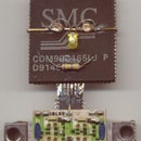
This is a stereo power amplifier of about 6W per channel (according to the manufacturer of the chip, Texas Instruments) which has a remarkably low component count.
The chip, two large electrolytics, and three smaller capacitors will make the amplifier complete. I am adding an output socket too, on board. The input shall be via a stereo cable and there has to be a 12 Volt supply line, as well.
The picture is of the major components arranged on a blank piece of PCB.
Step 2: Populated Board

The rest of the components have been placed on board. The chip is soldered upside down, dead bug style, and the exposed thermal pad can have a small heatsink soldered to it.
The capacitors are connected with flexible wire taken from Hard disk flat cable, and so the input capacitors can move and short out. They shall be placed in position and encapsulated in hot melt glue.
Step 3: Ready for Potting

The ends of the capacitor leads have been bent up so that they will be accessible after "potting". Hot glue easily melts when the component lead is heated with a soldering iron, so alterations would be easy.
If the regular epoxy potting compound is used, this won't be that easy.
A sort of enclosure is made by taping thick paper around the board, and the hot melt glue melted and flowed around the components using my hot air tool fitted with a narrow nozzle.
Step 4: The Finished Board

This is the finished board.
A red LED has been added to indicate power. A zener diode protects against reverse polarity and excess voltage. Some copper foil has been soldered to the thermal pad of the chip.
The components are held immobile by the hot melt glue, yet they may be rearranged by heating using a soldering iron.
The chip is rated to work for supply voltages between 9.5 volts and 18 volts. The zener is of 18 volts. It will conduct if the voltage is applied in reverse, or if the voltage goes above 18 volts.
It might fail short circuit if the fault current is too high, thus protecting the chip. It has been mounted outside the hot glue, to be easily replaced.
Step 5: Component Layout

This is the component layout, should repairs be needed.
Or if somebody wishes to duplicate this project.
Step 6: Connections Labelled

The power and signal inputs are to be connected by the user. I have labelled the points by attaching piece of paper over the connections.
The completed board fits into the shell of a 9V PP3 battery.
Step 7: It Would Look Like This ...

When fitted into the shell of a PP3 battery. The power and signal cables can exit the other way, making it an "in-line" module. Or else it can be brought out this side itself, allowing the module to be placed on a table upright.


