Introduction: A Reed Switch
Reed switches activated by a passing magnet are often used to send pulses to a bicycle speedometer so speed and distance can be displayed. I have a digital bicycle speedometer, but the reed switch sensor has been lost and I want to put it onto my granddaughter's "new" bicycle.
Radio Shack is gone. Home alarms use magnets and reed switches to detect open doors and windows. I thought I would pick up one of those for around $3 US, but the style has changed and the new version costs around $10.
I found a couple of Instructables and a couple of videos on making a reed switch. I thought I could do better, and decided to offer what you see here.
Tools
- Hot glue gun
- Tin shears
- Wire cutter
- Needle nose pliers
Materials
- An old tape measure
- Solid copper wire
Step 1: A Key Difference
The first photo shows a tape measure that no longer retracts into its case. The tape has been "broken" and folds back on itself.
Most home built reed switches use the flex in a piece of wire to return the switch after the magnet is out of proximity. I checked a piece of steel wire, but it would have been very long to get the movement I wanted. I wanted something made to be springy so it will not fatigue after many cycles. I cut a piece of the measuring tape about 2 inches long and put it into a vise. See the second photo. I brought a magnet near to the metal tape, and it deflected. It also snapped back to its original position when the magnet was removed.
Step 2: Preparing the Measuring Tape
I cut the tape lengthwise to make its width thinner so it will be more responsive to a weaker magnet. Later I further reduced the width by about a third.
I used sandpaper to remove the painted surface so it will conduct electricity and make good contact. I removed paint from the opposite end, too; but, from the opposite side.
Step 3: Copper Terminal
I cannot solder to the steel in the measuring tape. Although not a perfect solution, I bent bare #14 solid copper wire around the bare end of the measuring tape and crimped it hard. Later I covered this with hot glue, in part to keep oxygen from the joint.
Another option would be to wrap the steel tape with a turn or two of bare copper magnet wire. It would need to be thick enough, but not so thick that it hinders the free movement of the measuring tape. Connections would be made to its tail.
Step 4: Prepare for the Other Conductor
A magnet passing a reed switch to create a pulse should pull one of the conductors into the other. One conductor should be ferrous metal that responds to a magnet, but the other should not. This reed switch will have steel (ferrous metal) and copper.
Notice I have insulated one of the conductors with electrical tape.The second conductor is a piece of copper wire. See the second photo. I taped the second conductor to the assembly for the first.
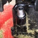
I found the tape does not do a complete job of holding the parts of the switch, and replaced it with hot glue as in the photo with the Introduction.
Step 5: Testing
This is a preliminary test. An Ohmmeter has been connected to the two terminals of the switch. I moved the switch nearer to the magnet. In the first photo the magnet is far enough away from the magnet that the switch has not closed and the meter shows an open circuit. The second photo shows the switch about 3/8 inch away from the magnet, but close enough to this magnet that the switch has closed to make a circuit and register on the meter.
What I need yet to do--
I need to make a protective case for my reed switch, but it needs to be thin on the side where the magnet is located. The magnet cannot be too far away if the switch is to work. PVC would be too thick. My case also needs to serve as a physical mount that allows me to put it exactly where I need it to be. I will want to be able to access the electrical contacts in case they oxidize and no longer conduct, or in case I need to tune the distance between the contacts for a better response.


