

Introduction: A Tiny Alarm System Using a Super Tiny Arduino Compatible Board!


Hello, today we are going to make a tiny cool project. We are going to build a tiny alarm device that measures the distance between itself and an object in front of it. And when the object moves past a set distance, the device will notify you with a loud buzzer noise.
To make a tiny alarm device, we need tiny components, that is why we used PICO as our microcontroller, as it fulfills our needs while being very small in size. We also used commonly used components to read the distance and give a signal to the buzzer. This project will take you around 45 minutes to finish, if you chose to use the provided code.
Step 1: Components
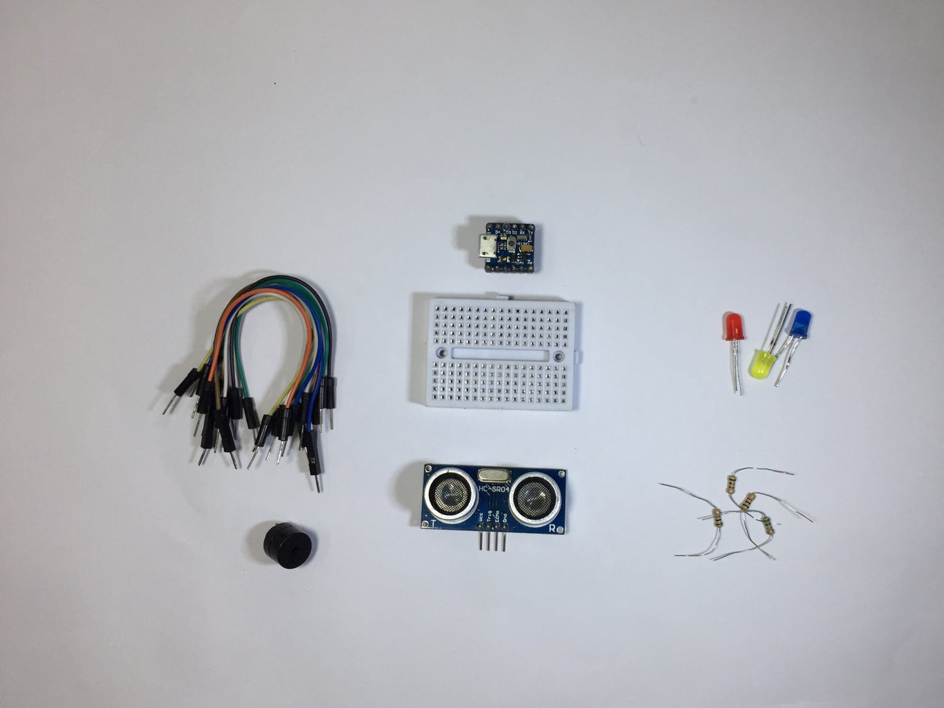
- 1 PICO board, available on mellbell.cc ($17)
- 1 ultrasonic sensor, ebay ($1.03)
- 1 small buzzer 5~6 volt, a bundle of 10 on ebay ($1.39)
- 3 LEDs 5mm (different colors), a bundle of 100 on ebay ($0.99)
- 4 330 ohm resistors, a bundle of 100 on ebay ($1.08)
- 12 jumber wires, a bundle of 40 on ebay ($0.99)
- 1 mini breadboard, a bundle of 5 on ebay ($2.52)
Step 2: How Ultrasonic Sensors Work


Before you connect the ultrasonic sensor and use it, let's learn how it works:
- First, it sends out an Ultrasonic wave from the transmitter transducer (left Transducer). If there is an object in front of the sensor, the waves hit that object and return back to the receiver transducer (right transducer)
- Then, the microcontroller calculates the time between sending the waves and receiving them. After that, the microcontroller does some mathematical calculations and gets the distance between the sensor and the object in front of it.
- This is the formula used to get the distance in CM: (duration / 2)/29.1 (You can find the math behind this formula in the picture above).
Step 3: Interfacing the Ultrasonic Sensor With PICO


The first thing to do, is to take a look at your PICO and see what you can do with it. And as you can see, PICO has 5 digital I/O Pins, and 3 analog input pins. Which will be used as follows:
Ultrasonic sensor pin outs:
- VCC (Ultrasonic Sensor) ---> VCC (PICO)
- GND (Ultrasonic Sensor) ---> GND (PICO)
- Trig (Ultrasonic Sensor) ---> A1 (PICO)
- Echo (Ultrasonic Sensor) ---> A0 (PICO)
Now all you need is to connect the ultrasonic sensor with PICO and make sure that everything is perfect.
Step 4: Ultrasonic Sensor Sketch

You now have to create a program, that takes the distance measured by the ultrasonic sensor, and display it on a serial monitor. So that you can get readings and make sure that everything is connected and working properly.
Create a function called measuredDistance that is responsible for measuring the time between sending a signal and receiving it, and calculating the distance. You also have to display the readings on your serial monitor, so that you can debug the project in the IDE.
You can download the attached program, if you don't want to write it yourself. You can also see how the serial monitor's readings should look from the image above.
Attachments

Step 5: Connecting the Buzzer


Now, that you have your sensor giving the distance between itself and any object in front of it. You have to do something with the readings, and as we said before, you are going to have a buzzer make a loud noise when the object in front of the sensor gets way too far.
Working with buzzers is very simple, as they only have two states of operation, either ON or OFF. They also have only two legs, one is positive (long leg), and the other is negative (Short Leg).
- When 5V is applied to the buzzer, it switches on and makes the loud buzzing noise.
- When 0V is applied to the buzzer, it switches off and no buzz is made.
Step 6: Programming the Buzzer

You want the buzzer to start buzzing when the object in front of the sensor gets further than 20CM, and turn off when the object is closer the 20CM “You can use whatever distance you want”.
The attached program contains the code that gets the readings from the ultrasonic sensor, and sends orders to the buzzer. Which are to start making noise when the object is further than 20CM, and to stop when it is closer than that.
Remember that you can customize the code to whatever rules and distances that you want.
Attachments
Step 7: Connecting the LEDs


Now, you want to add three LEDs to your project to make it more interactive and dynamic.
We used regular 5mm LEDs, and these only have two legs, a positive (long leg), and a negative (short leg). And when we apply 5V to the led it turns on when we apply 0v it turns off. You can use whatever types of LEDs that you wan here, and if you have any questions about that, feel free to ask them.
Step 8: Programming the LEDs

We used 3 LEDs in our project, and they light up depending on the distance between the sensor and the object in front of it.
The blue LED will turn on when the distance is less than 10cm. The Yellow LED will turn on when the distance is between 10 cm and 20cm. The red LED will turn on when the distance is greater than 20cm.
And again, remember that you can customize the rules that control how your LEDs light up.
Attachments
Step 9: Connecting the Power Source


At this stage, you want the ability to use your tiny alarm without being forced to connect it to a PC. So, add a 9V battery to your project and connect it to your PICO.
- Positive red wire(Battery) ---> Vin (PICO)
- Negative black wire (Battery) ---> GND (PICO)
And now, your alarm system will be operational without having to be connected to a PC.
Step 10: You Are Done!
Congratulations! Now you have a device that alerts you based on the distance of the object in front of it. Also, don't forget that you can customize its rules, and change how and why the buzzer makes a sound.
You can find us on our Facebook page, and on mellbell.cc. And please feel free to ask any questions, we will be glad to answer them :)


