

Introduction: A Reliable Plasma Speaker


I've seen multiple designs for a plasma speaker online, and quite frankly most of them suck. Some problems I noticed were constantly blowing up MOSFETs, distorted audio, excessive heating of the MOSFET(s) etc.
So, In this instructable I'll show you how to build the speaker that's on my website. Properly heat-sinked it'll be able to run continuously; I have run mine for a length of about 6 hours with no problems.
Step 1: Gather the Parts
You'll need some parts for this speaker, not too many but some.
You'll need:
Components:
4x UF4007 diodes
4x 12 volt zener diodes
2x IRFP250 mosfets. You can also use some better fets, the lower the Rds On the better. Just make sure they can handle at least 200V, flybacks make some nasty back EMF.
1x SG3525 IC
1x LM7812
2x 22 ohm resistors
1x 2.2k resistor
1x 10k pot
2x 0.1uF (104) capacitors
1x 3.3nF (332) capacitor
1x 1uF (105) MKP capacitor
1x 2.2uF electrolytic capacitor
2x 10,000uF electrolytic capacitors If you use 40v 8000uF caps instead you can apply 36V and make the arc even bigger and louder. Just make sure to replace the 7812 with a 7815 or a 7818.
Other components:
A flyback transformer. You can get these out of old computer monitors, TVs etc.
A ferrite toroid. These may be inside computer monitors, but if you can't find one get it here.
Some 18ga wire.
Some 24 ga wire, the wire from inside of a telephone cable works great.
2 heat sinks, you can get them from a computer monitor. You'll need to use your scavenging abilities here. If you use 1 heat sink make sure you use some insulating pads.
Thermal goop.
Step 2: Making the GDT

The gate drive transformer is a part you'll need to make yourself. It consists of 3 strands of wire wrapped >14 times around a ferrite core. It's not much of an exact science, just wrap it all nice and neat. Use the 22ga wire for this.
Step 3: The Circuit

I know that some of you people aren't very electrically minded, so I decided to make a circuit diagram that is very easy to follow. For those that do understand schematics, here's one.
Step 4: Breadboards

Breadboards are relatively cheap, and it's a great investment. Breadboards have one flaw though; some parts have either pins that are too big to fit in the holes or they must be attached to a heat sink. To use these parts I recommend just soldering wires to them. Soldering isn't hard, but it's the best way to connect things. There are plenty of soldering guides on the interwebs.
Make sure you put a pin on the ends of the wires so they can plug into the breadboard. Also make sue you use heat sink goop (and insulators if 2 fets share a sink).
Step 5: Prototyping the Circuit

Just hook it all together! It doesn't need to look nice, it just has to work.
There's an important note on the next step regarding the gate transformer.
Step 6: Phasing the GDT

You must make sure the GDT is properly phased. Phasing is the direction of the transformer's windings. You must make sure that one output winding is reversed; this reverses the signal that it puts out. The purpose of the GDT is to isolate the mosfets from the chip.
The mosfets are supposed to "flip flop" --one turns on as the other turns off. This means the gate signals of the fets are supposed to be opposite. If both the signals are the same, both the mosfets will turn on at the same time and they short circuit or possibly explode.
You want one signal inverted and to do that you reverse a winding; that inverts the signal.
A picture will better explain what I'm talking about. Also, make sure the wire in the middle is the one that's connected to the IC.
Step 7: Initial Tests

For the initial test I recommend using a power supply that can't supply over 9000 amps. Unless you are confident that you have everything hooked up correctly I'd use a computer power supply to test it initially. Computer power supplies are current limited, and that means if you f*ck up and both of your mosfets turn on at the same time the PSU will detect a short circuit and turn off, saving your $2 FETS.
There are many guides on modifying computer power supplies to be used as bench supplies, and here's one of them.
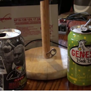
Test your circuit by taping a drinking straw to the high voltage wire on your flyback. Then apply the power to the circuit and hope nothing blows up. If everything is OK use that straw to move the high voltage wire to the pins on the bottom of the flyback. You should be able to arc to at least one of the pins. If nothing happens you did something wrong.
Make a note about which pin the electricity arcs to best. This is your ground pin.
Since this is only 12 volts and limited amps don't expect anything impressive. You're just making sure thing work.
Step 8: Apply the Juice!

Alright now it's time for the big guns: Lead acid batteries. These things can supply over 9000 amps and they have no electrical noise whatsoever. They are usually 12 volts so you're going to need 2 of them.
You can either use car batteries or AGM batteries. I prefer the AGM ones because they are smaller and you can't spill them. A 12V 8Ah AGM battery usually sells on eGay for about 10 to 15 dollars. Lead acid battery chargers can be bought cheap on eGay too. Although batteries are not too cheap, they will become one of your most used "tools" if you start playing with circuits.
Put them in series to get 24V.
When you apply the juice to your circuit the arcs will be hotter and longer. Apply music to the circuit. You'll need a "clean" music source; an ipod makes tons of electrical noise. I used the sound card from my computer, some mp3 players may work too. Turn the volume all the way down and then up a little because too loud a signal can kill the IC. Plasma speakers aren't too loud so you'll need a quiet room to hear it.
Turn the pot until distortion of the music is at its lowest.
Step 9: Make It Last

To make the thing last you'll want to put it on a perfboard. These are pretty much blank circuit boards with plenty of holes. Buy perfboard, not vero or strip board. Strip/vero board is a PITA to use.
Once again, perfboarding has been covered by others.
Have fun!
Second Prize in the
Epilog Challenge


