

Introduction: ATMega328P Rotary Encoder and 7-Segment Display


In this Instructable, I am going to show you a rather simple way to use a rotary encoder to control the output of a three digit, seven segment display. We're going to use Interrupt Service Routines (ISR) to handle the input from the rotary encoder and a Serial-in, Parallel-out (SIPO) shift register to handle the output to the display. We'll also address the very important issue of debouncing when using inexpensive rotary encoders and explore multiplexing to drive our display. So, let's get started!
Step 1: Gather Your Parts

We're going to build this using the bare ATMega328P but if you only have Arduino UNO, you won't need the 22pF ceramic capacitors, the 16.00 MHz oscillator, or the CH340G USB to TTL as all of these are built into the Arduino board. But if you do want to be adventurous, these are the parts you need:
- Atmel ATMega328P
- SN74HC595 Serial-in Parallel-out Shift Register
- CD4511BE BCD (Binary Coded Decimal) to 7-Segment Display Driver
- 3x 2n3904 General Purpose NPN Transistors
- Mechanical Rotary Encoder (These have 20 dentents per revolution but any number will work)
- 16.000 MHz Crytal Oscillator
- 2x 22pF Ceramic Capacitors
- 2x 10,000pF (104) Ceramic Capacitors
- Normally Open (NO) Tactile Push Button
- 3x 10K Ohm Resistors
- 3x 1K Ohm Resistors
- 3x 100 Ohm Resistors
- CH340G USB to TTL Programmer
- A bunch of jumper wires (not shown)
Just as a note, I am running Ubuntu so the CH340G just worked, I'm not sure if you need to load drivers for it on Windows.
Step 2: Sanity Check


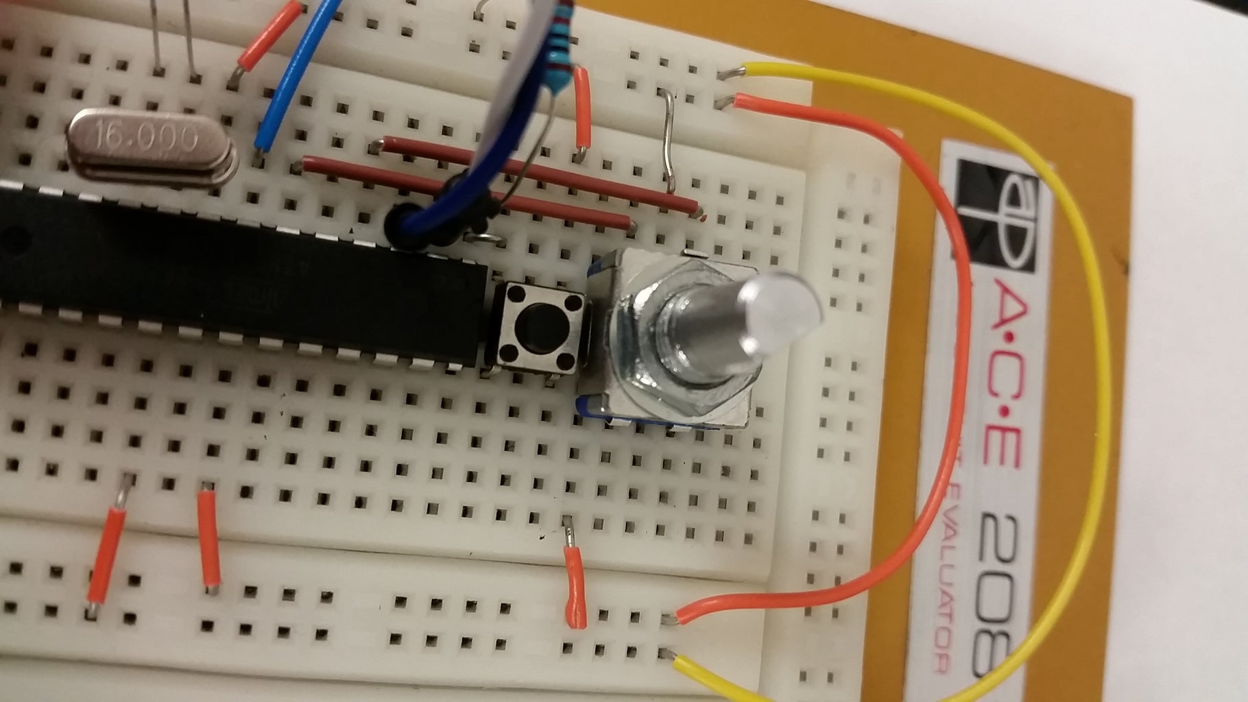
First thing to always do is make sure the basics work. We'll place the ATMega on our breadboard and wire it up, then upload and run the classic blink sketch. Since we aren't using an Arduino board, we need to know which pins are which since they do not line up as one may think (ATMega physical pin 13 != Digital I/O pin 13). If you plan on using the bare chip more often, I strongly recommend printing out the pinout sheet for easy reference. Go ahead and place the components and wires as shown in the picture and upload the blink sketch (I forgot to add the LED in the parts list but hopefully you have a few spares lying around!).
- The reset pin (physical pin 1) needs to be pulled high via a 10K Ohm resistor and the tactile push button wired to ground. If using the same CH340G board, you must manually reset the board at just the right moment during upload. The winning combination I found was to click upload in the IDE, wait for it to finish compiling and the hit reset as it start to upload. It'll take a little practice to get the timing down but once you have it, it's like riding a bike.
- Make sure to wire the RX pin on the chip (physical pin 2) to the TX pin on the CH340G and the TX -> RX. Don't ask how long/how much frustration it took to figure that one out.
Once you have you LED blinking, it's time to push on!
Step 3: The Rotary Encoder


Add the rotary encoder to the bread board and install the resistors and capacitors as shown in the schematic. Make sure to connect the "clock" pin of the rotary encoder to physical pin 4 or digital pin 2 as this is one of the hardware interrupt pins. Then, connect the other signal pin from the rotary encoder to physical pin 6. We'll save the other hardware interrupt pin (physical pin 5) for something else such as the push button built into the rotary encoder. My attempted schematic shows all of the basic connections and then there is also a better schematic of the rotary encoder itself. Note: the blue and yellow rotary encoder schematics shows two 10K Ohm pull up resistors, but fortunately the ATMega has some built in pull up resistors that we'll use instead. The third image shows a simple low pass filter we'll use as a hardware debounce circuit that works tremendously well as we'll see later.
Step 4: Seven Segment Display Drivers


To drive the 7-segment display, we'll need to IC's:
- SN74HC595 Serial-in Parallel-out Shift Register
- CD4511BE BCD (Binary Coded Decimal) to 7-Segment Display Driver
We'll wire the shift register to the ATMega digital I/O (DIO) pins 5, 6, 7 as follows:
DIO -> Shift Register
5 -> 12 - Storage Register Clock (Latch)
6 -> 14 - Serial Data Input
7 -> 11 - Shift Register Clock
Then, follow the schematic to make the rest of the connections between the ATMega, Shift Register and BCD Decoder. When wiring the BCD Decoder to the 7-Segment display, refer to the pinouts provided. The letters at the output of the BCD Decoder correspond to the labels of the 7-segment display and should be hooked up accordingly, ie. a -> a, b -> b. When connecting the Shift Register to the BCD Decoder, Q0 -> Q3 connect to D0 -> D3 respectively. Unfortunately there was not a pre-made IC for the CD4511BE so I had to mak a generic IC but all of the connections line up properly with the appropiate pins. Also note that the Shift Register bit 8 (Q7) controls the decimal point.
The value chose for the transistor bases was 1KOhm for the second and third digits and 10KOhm for the first to level out the brightness; a kind of haphazard fix for the issue. Finally, I used a 1KOhm trimmer pot to control the total brightness of the displays. You could use a single fixed resistor if you want a static brightness and remember: since they are multiplexed, only one segment will be on at any moment.
Step 5: The Code

The code is hosted on GitHub and can be found here:
https://github.com/ecramirez94/Arduino_RotaryEncoder_SevenSegmentDisplay.git
Step 6: The Final Product
That's all there is to it! If you have any questions, want a better explanation or to know more about any part of the project please comment below!


